Process LC (Loosely Coupled) and TC (Tightly Coupled)
Loosely coupled processing is not supported in Inertial Explorer Xpress, GrafNav or GrafNav Static.
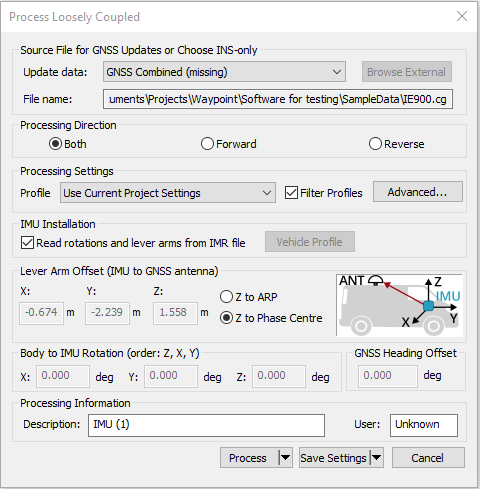
This window provides access to most settings related to IMU processing.
Update Data
Use this option to select the GNSS file from which Inertial Explorer obtains updates. In most cases, the differential combined solution is suggested. However, you may specify an alternate file by selecting External trajectory from the drop-down menu and clicking the Browse External button.
File Name
Displays the selected file that will be used for updates.
Process Settings
Profile
A processing profile is automatically loaded based on the detected processing environment (airborne, UAV, marine, ground vehicle, pedestrian) when converting the raw GNSS data to GPB format and the type of SPAN system used. If the automatically detected processing profile is incorrect it can be changed by accessing the pull down menu.
Filter Profiles
This option, enabled by default, will only show profiles associated with the SPAN IMU in use. If using third party IMU data, this option should be disabled in order to gain access to custom processing profiles.
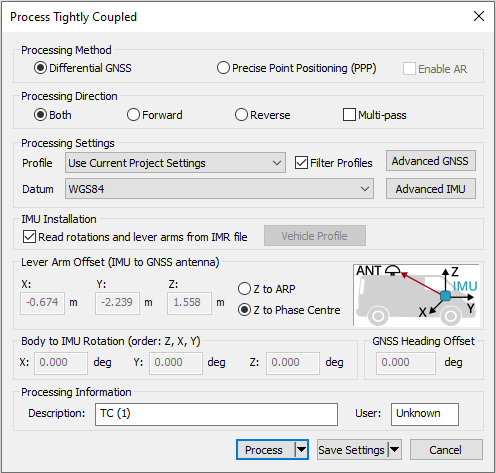
Datum (TC processing only)
Choose the processing datum for all processed output here. If any base stations have been entered in a different datum, the coordinates will be automatically converted to the processing datum. Users may change their default processing datum in the Solution tab of Preferences window. See Solution.
Advanced...(LC Processing)
This button provides access to all IMU processing settings.
Advanced GNSS (TC Processing)
This button provides access to all GNSS processing settings. Refer to Process GNSS for information.
Advanced IMU (TC Processing)
This button provides access to all IMU processing settings.
IMU Installation (IE/IEX only)
Read rotations and lever arms from IMR file
If using a NovAtel SPAN system, the IMU to GNSS lever arm and body to IMU rotation may be set during data collection. If this has been set and the necessary log (INSCONFIGB) is present in the raw data, this information is imported automatically to Inertial Explorer.
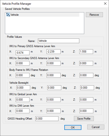
Vehicle Profile
This button accesses the Vehicle Profile Manager. It allows the primary lever arm, secondary lever arm, body to IMU rotation, vehicle boresight, gimbal lever arm, DMI lever arm, and GNSS heading offset to be saved to a vehicle profile. This facilitates quick and easy loading of important project parameters that are specific to each survey vehicle.
It is not necessary to save vehicle profiles if using a NovAtel SPAN system as this information can be retrieved directly from the raw data and imported automatically. Vehicle profiles are intended to assist non-SPAN customer workflow.
Lever Arm Offset (IMU to GNSS Antenna)
To perform GNSS updates accurately, enter the 3-D offset, in meters, from the IMU sensor array’s navigation center to the GNSS antenna. This offset vector must be entered with respect to the body-frame of the vehicle, as Figure: Body Frame Definition for Lever Arm Offset shows.
You must also specify whether the Z value applies to the antenna's reference point (ARP) or L1 phase center. To specify ARP, you must select an antenna model when you add the remote GPB file to the project. In this case, the antenna model's offset value is applied to the Z value to raise the Z value to the L1 phase center.
Save lever arms for future access using the Vehicle Profile button.
Read rotations and lever arms from IMR file
If the lever arm and body to IMU rotation values are written to the header of the IMR file, then use this option to extract them.
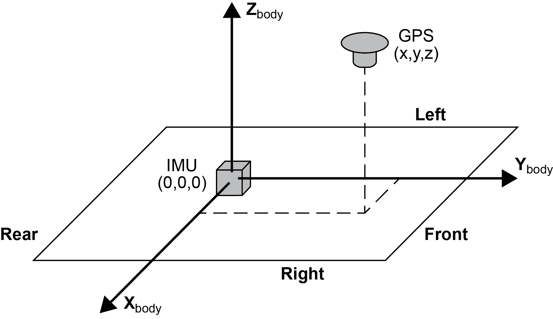
The IMU is the local origin of the system and the measurements are defined as the following:
X: The measured lateral distance in the vehicle body frame from the IMU to the GNSS antenna.
Y: The measured distance along the longitudinal axis of the vehicle from the IMU to the GNSS antenna.
Z: The measured height change from the IMU to the GNSS antenna.
All measurements are from the navigation center of the IMU to the GNSS antenna.
Body-to-IMU Rotations (Rotate Vehicle Frame into IMU Frame) (IE/IEX only)
Many typical IMU installations have the surface of the IMU directly attached to the floor of the vehicle so the sensor frame of the IMU and the body frame of the vehicle are more or less aligned. In these installations, the roll, pitch and yaw of the vehicle are directly sensed by the IMU. Some IMUs are installed in a tilted position with respect to the body frame of the vehicle. If the tilt between the IMU frame and body frame is known, Inertial Explorer compensates so that the attitude information produced is with respect to vehicle body frame, not the IMU sensor frame.
The order of rotations employed is Rz, then Rx, followed by Ry, in decimal degree units.
GNSS Heading Offset (IE/IEX only)
This value may also be referred to as the "Reference to Aircraft Rotation" and is meant for customers that have backwards-pointing LIDAR applications or other specialized applications where the IMU cannot be rotated to the vehicle frame through body to IMU rotations. This option applies a correction (as entered in degrees) to GNSS Course Over Ground (COG) values in order to allow kinematic alignments to succeed when the IMU is intentionally not aligned to the vehicle frame. This option has no effect if a static alignment is performed.
Advanced IMU (IE/IEX only)
This button provides access to all IMU processing options.