Updates (IE/IEX only)
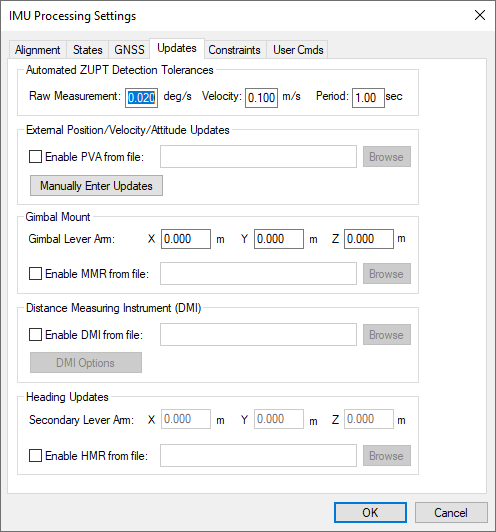
Automated ZUPT Detection Tolerances
These settings control the software's ability to detect periods of zero velocity.
Raw Measurement
The raw gyro measurement threshold. This value may need to be raised for lower-grade sensors (i.e. MEMS) to accommodate the noisier measurements.
Velocity
The GPS velocity threshold. Potential ZUPTs are rejected if the GNSS-derived velocity exceeds this value.
Period
Length of time span over which measurements are averaged.
External Position/Velocity/Attitude Updates (IE only)
A binary PVA file can be input to Inertial Explorer if external position updates are available. See PVA File for the format of this file. Input of this binary file is the recommended approach if large numbers of external updates are available. Two types of updates are supported by the PVA file: absolute coordinate and relative coordinate updates. Absolute updates are position updates within a defined reference frame, and the relative updates provide the translation vector between two points in time.
Absolute Updates
Absolute updates are typically formed from either a robotic total station or with an optical or LIDAR sensor and ground control. Inertial Explorer needs these updates and the IMU center. If the positions are with respect to another sensor location, then a lever arm with the offset can be set.
Relative Updates
Inertial Explorer can accept relative position updates that have been measured by an external sensor, such as a camera-array and/or LIDAR sensor. For the photogrammetric case, knowledge of scale (or depth) is important, which becomes difficult with monocular vision systems. Therefore, stereo vision systems with sufficient base (camera separation) is suggested. In the case of LIDAR, a sufficient number of surfaces that are perpendicular to the direction of travel need to be present, or preferably estimated accuracy values will compensate for geometry variations. Regardless of the input source, the relative position inputs will have varying accuracy, depending on the number and geometrical distribution of matched points. Thus, computing representative standard deviations is highly recommended.
Relative updates are measured vector components between two timed events, which are determined by an external system that is time-synchronized with the navigation system. Basically, the sensor measures the relative motion and orientation between the two epochs, which are generally 0.2 s to 2 s apart. The best data-rate for the formation of the updates and the best rate for input into Inertial Explorer may differ, where Inertial Explorer may benefit from a lower rate. The problem with very short intervals is that the noise (measurement error) can be a significant portion of the vector length. Therefore, an external pre-processor may need to accumulate high-rate measurements to a lower rate like 1 Hz, which is suitable for Inertial Explorer.
The coordinate system supported for the relative updates is local level frame. The input y-axis is aligned to true-north, x-axis to east and z-axis to up. The local level vector frame changes as the rover position moves, and for the update the local level frame is computed at the update time. It is critical that the local level frame is recomputed for each update.
Manually Enter Updates (IE only)
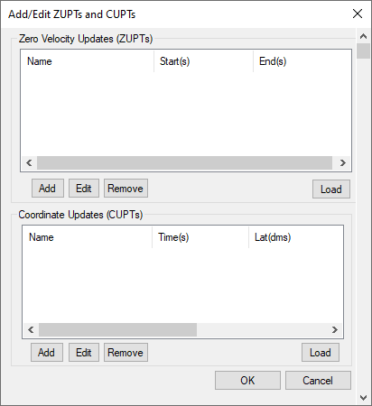
Inertial Explorer also accepts input of individual ZUPTs and CUPTs through the Manually Enter Updates button. This feature is more convenient for customers that want to manually enter a small number of such updates as opposed to having to format your own binary file. This feature also supports loading of ZUPTs and CUPTs from an ASCII file, however this feature is limited to supporting a maximum of 1000 updates. For this reason, using the binary PVA file is encouraged when large numbers of external updates exist.
Zero Velocity Updates (ZUPTs)
Inertial Explorer automatically detects ZUPTs by analyzing the GNSS, IMU and, if available, DMI data. This is true for both loosely and tightly coupled processing. As such, the manual entry of ZUPTs is generally not necessary, except in cases of poor data quality. Nonetheless, individual ZUPTs can be added here or loaded from an ASCII file.
External coordinate updates can be very beneficial to GNSS/INS post-processing in areas of denied GNSS signal reception if they can be properly time tagged. This dialog can be used to add individual time coordinate updates or load from an ASCII file.
Gimbal Mount
Gimbal mount updates are not supported on Inertial Explorer Xpress, GrafNav or GrafNav Static.
If using a gimbal mount, the IMU to gimbal center lever arm can be entered here. This should be entered in the vehicle frame (Y-forward, X-right, Z-up) with the origin at the IMU center of navigation. This causes Inertial Explorer to shift it's output from the IMU to the Gimbal Center.
MMR files are automatically produced by the SPAN data converter and contain the rotations of the stabilized gimbal platform. This is required in order to properly compensate for the changing IMU to GNSS lever arm during operation of the gimbal unit.
Distance Measuring Instrument (DMI)
DMI updates are not supported on Inertial Explorer Xpress, GrafNav or GrafNav Static.
If logging DMI data, the NovAtel SPAN decoder will automatically write a DMR file which contains time stamped DMI measurements. If a DMR file is detected during project creation, it is automatically loaded into the project and thus does not have to be explicitly set here.
DMI Options
A typical DMI will either output an accumulated tick count or a measured speed. If accumulated tick counts are recorded, Inertial Explorer converts them to a velocity update using knowledge of the ticks/rev, wheel circumference, and estimated wheel circumference scale factor. If speed was recorded, then the software applies the update directly as a velocity update.
Detect ZUPTs from DMI sensor
This option is off by default as Inertial Explorer already has two layers of ZUPT detection; analysis of the raw IMU measurements and using available GNSS data. This option therefore is generally not needed and if the DMI used does not function well at low velocity, it can actually be harmful.
If however a high resolution DMI is used which works well at low velocity and if ZUPTs will be observed during periods of extended GNSS outages, this option can be very beneficial in helping to observe ZUPTs.
Measurement standard deviations
The standard deviation associated with the DMI measurements depends on the DMI being used. As such, this value may need to be determined empirically.
Wheel circumference
The default value is 1.96 meters if no value is detected from the raw GNSS data or set during conversion. Inertial Explorer computes a DMI scale factor to account for varying wheel sizes during data collection, however the best estimate possible of the wheel circumference should be input.
Heading Updates
If using the NovAtel dual antenna ALIGN system and requesting HEADING2B logs, an HMR file is automatically produced during data conversion which can be input to Inertial Explorer here. The secondary lever arm must also be set if using it in Dual GPS Antenna System mode.
Heading updates are most useful in assisting auto/kinematic alignment in low dynamic applications such as marine surveys. When a kinematic alignment is used and heading updates are available, Inertial Explorer will extract the initial heading of the vehicle from the HMR file.
The HMR data format is described in HMR File.