Connect an OEM-IMU-µIMU-IC-UART directly to an OEM7 receiver
The OEM-IMU-µIMU-IC-UART can connect directly to an OEM7 receiver using a serial port connection.
The OEM-IMU-µIMU-IC-UART serial port uses RS-422 signal levels. Since most OEM7 receiver card ports use LVCMOS signal levels, an RS-422 line driver is needed to convert from LVCMOS to RS-422. The exception is COM1 on the OEM729 that operates at RS-232 or RS-422 levels.
The interface to the OEM-IMU-µIMU-IC-UART must provide:
-
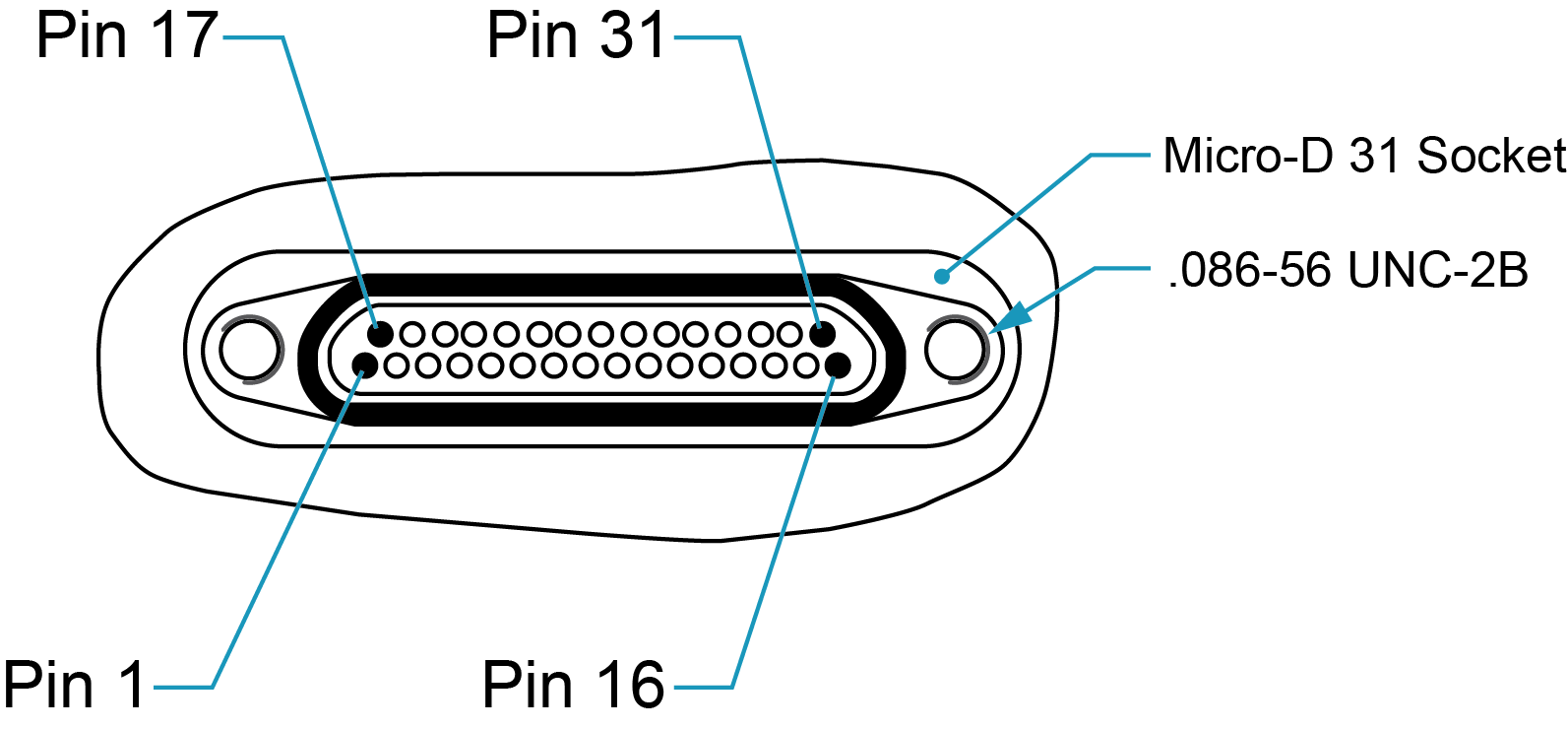
a Micro-D 31 pin male connector
This connector mates with the connector on the OEM-IMU-µIMU-IC-UART. See Figure: OEM-IMU-µIMU-IC-UART pinout.
-
an RS-422 serial port connection to the OEM7 receiver
For most OEM7 receiver cards, the connection must include an RS-422 line driver.
If using COM1 on an OEM729, an RS-422 line driver is not required. However, the COM1 protocol must be set to RS-422 using the SERIALPROTOCOL command.
Use COM1 or COM2 on the PwrPak7 to connect to the OEM-IMU-µIMU-IC-UART. These ports can be set to RS-422 protocol using the SERIALPROTOCOL command.
-
a 5.0 VDC (±0.5 VDC) regulated power supply
Install a user supplied 2.5 A slow blow fuse to the positive pole of the power source to protect the power supply wiring and your warranty.
-
a 3.3 V differential to single ended transceiver for the SYNC signal
Refer to Table: OEM7 receiver card to OEM-IMU-µIMU-IC-UART pin connections or Table: OEM729 COM1 or PwrPak7 to OEM-IMU-µIMU-IC-UART pin connections for the connections required between the IMU and receiver.
OEM-IMU-µIMU-IC-UART pinout

Pins not shown on the following tables are not connected.
OEM7 receiver card to OEM-IMU-µIMU-IC-UART pin connections
|
|
|
|
|
|
|
|
|
|
|
|
|
1-2
|
GND
|
–
|
–
|
–
|
Any receiver ground pin
|
|
3
|
DATA_P
|
RS422 B+
|
–
|
–
|
Part of RS-422 transmit pair from the µIMU UART
|
|
4
|
DATA_N
|
RS422 B-
|
–
|
–
|
Part of RS-422 transmit pair from the µIMU UART
|
|
7-8
|
GND
|
–
|
–
|
–
|
Any receiver ground pin
|
|
16
|
SYNCOUT_N
|
–
|
–
|
EVENT_IN2
OEM719: 7
OEM7600: 29
OEM7700: 29
OEM7720: 29
|
Part of the differential sync signal (ToV) pair from the µIMU UART.
The SYNCOUT_N and SYNCOUT_P are an RS-422 compatible differential pair and must be converted to a 3.3 V single ended signal before being input to EVENT_IN2.
|
|
17-19
|
5V Pwr
|
–
|
–
|
–
|
5 VDC power supply
|
|
20-22
|
GND
|
–
|
–
|
–
|
Connect to power supply Ground. Follow grounding best practices.
|
|
30
|
RESETIMUx
|
–
|
–
|
–
|
Recommended to connect to a “power good” signal from 5V power supply. May be left no connect if “power good” signal is unavailable.
|
|
31
|
SYNCOUT_P
|
–
|
–
|
EVENT_IN2
OEM719: 7
OEM7600: 29
OEM7700: 29
OEM7720: 29
|
Part of the differential sync signal (ToV) pair from the µIMU UART.
The SYNCOUT_N and SYNCOUT_P are an RS-422 compatible differential pair and must be converted to a 3.3 V single ended signal before being input to EVENT_IN2.
|
|
–
|
–
|
–
|
LVCMOS B IN
|
COMx_RXD
|
Any receiver COM port receive pin
|
|
–
|
–
|
–
|
GND
|
|
Any receiver ground pin
|
OEM729 COM1 or PwrPak7 to OEM-IMU-µIMU-IC-UART pin connections
|
|
|
|
|
|
|
|
|
|
|
1-2
|
GND
|
–
|
–
|
Any receiver ground pin
|
|
3
|
DATA_P
|
OEM729 COM1: 18
PwrPak7 COM1: 3
COM2: 20
|
COMx_RXD+
|
Part of RS-422 transmit pair from the OEM-IMU-µIMU UART
|
|
4
|
DATA_N
|
OEM729 COM1: 15
PwrPak7 COM1: 4
COM2: 12
|
COMx_RXD-
|
Part of RS-422 transmit pair from the OEM-IMU-µIMU UART
|
|
7-8
|
GND
|
–
|
–
|
Any receiver ground pin
|
|
16
|
SYNCOUT_N
|
OEM729: 7
PwrPak7: 23
|
EVENT_IN2
|
Part of the differential sync signal (ToV) pair from the OEM-IMU-µIMU UART.
The SYNCOUT_N and SYNCOUT_P are an RS-422 compatible differential pair and must be converted to a 3.3 V single ended signal before being input to EVENT_IN2.
|
|
17-19
|
5V Pwr
|
–
|
–
|
5 VDC power supply
|
|
20-22
|
GND
|
–
|
–
|
Connect to power supply Ground. Follow grounding best practices.
|
|
30
|
RESETIMUx
|
–
|
–
|
Recommended to connect to a “power good” signal from 5V power supply. May be left no connect if “power good” signal is unavailable.
|
|
31
|
SYNCOUT_P
|
OEM729: 7
PwrPak7: 23
|
EVENT_IN2
|
Part of the differential sync signal (ToV) pair from the OEM-IMU-µIMU UART.
The SYNCOUT_N and SYNCOUT_P are an RS-422 compatible differential pair and must be converted to a 3.3 V single ended signal before being input to EVENT_IN2.
|
For the location of the receiver ground pins and transmit and receive pairs, refer to OEM719 interface connector, OEM729 interface connectors, OEM7600 interface connector, OEM7700 interface connector, OEM7720 interface connector or PwrPak7 connectors.
