PwrPak7 connectors
|
Connector |
Label |
Connector type |
Description |
|---|---|---|---|
|
|
ANT |
TNC |
Connects the receiver to the GNSS antenna (PwrPak7, PwrPak7-E1 and PwrPak7-E2) |
|
|
ANT 1 |
SMA |
Connects the receiver to the primary GNSS antenna (PwrPak7D, PwrPak7D-E1 and PwrPak7D-E2) |
|
ANT 2 |
SMA |
Connects the receiver to the secondary GNSS antenna (PwrPak7D, PwrPak7D-E1 and PwrPak7D-E2) |
|
|
|
COM PORTS |
RJ45 |
Connects the receiver to an Ethernet network |
|
|
USB Micro A/B |
A USB 2.0 port used to communicate from a computer to the receiver using a USB cable |
|
|
|
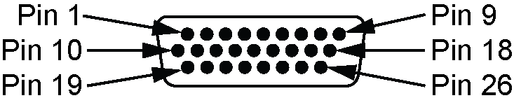
DSUB HD26 |
Provides access to communication signals on the receiver. This includes:
|
|
|
|
TRANSFER |
USB Micro A/B |
USB 2.0 port used to transfer files from the onboard memory to a USB stick or computer (PwrPak7Q variants do not have the TRANSFER port.) |
|
|
PWR |
SAL M12 5 pin |
Connects the receiver to the power supply |


|
Pin |
Signal name |
Description |
|---|---|---|
|
1 |
COM1_RTS/ COM1_TX- |
When COM1 is set to RS-232, this is the Request To Send flow control signal. When COM1 is set to RS-422, this is one half of the COM1 RS-422 transmit differential pair. |
|
2 |
COM1_TX/ COM1_TX+ |
When COM1 is set to RS-232, this is the COM1 transmit signal. When COM1 is set to RS-422, this is one half of the COM1 transmit differential pair. |
|
3 |
COM1_RX COM1_RX+ |
When COM1 is set to RS-232, this is the COM1 receive signal. When COM1 is set to RS-422, this is one half of the COM1 receive differential pair. |
|
4 |
COM1_CTS COM1_RX- |
When COM1 is set to RS-232, this is the COM1 Clear To Send flow control signal. When COM1 is set to RS-422, this is one half of the COM1 receive differential pair. |
|
5 |
Wheel Sensor A+ |
Signal A+ from the Distance Measurement Instrument |
|
6 |
Wheel Sensor A- |
Signal A- from the Distance Measurement Instrument |
|
7 |
Wheel Sensor B+ |
Signal B+ from the Distance Measurement Instrument |
|
8 |
Wheel Sensor B- |
Signal B- from the Distance Measurement Instrument |
|
9 |
CAN_H |
CAN bus port |
|
10 |
COM2_TX COM2_TX+ |
When COM2 is set to RS-232, this is the COM2 transmit signal. When COM2 is set to RS-422, this is one half of the COM2 transmit differential pair. |
|
11 |
GND |
Ground reference |
|
12 |
COM2_RX- |
One half of the RS-422 COM2 receive differential pair. |
|
13 |
COM3_TX |
COM3 transmit signal |
|
14 |
GND |
Ground reference |
|
15 |
EVENT_IN3 |
EVENT3 (Mark3) input |
|
16 |
EVENT_OUT1 |
EVENT1 (Mark1) output |
|
17 |
GND |
Ground reference |
|
18 |
CAN_L |
CAN bus port |
|
19 |
COM2_TX- |
One half of the COM2 transmit differential pair. |
|
20 |
COM2_RX COM2_RX+ |
When COM2 is set to RS-232, this is the COM2 receive signal. When COM2 is set to RS-422, this is one half of the COM2 receive differential pair. |
|
21 |
COM3_RX |
COM3 receive signal |
|
22 |
EVENT_IN1 |
EVENT1 (Mark1) input |
|
23 |
EVENT_IN2 |
EVENT2 (Mark2) input |
|
24 |
PPS |
Pulse Per Second output (Timemark) |
|
25 |
EVENT_OUT2 |
EVENT2 (Mark2) output |
|
26 |
EVENT_OUT3 |
EVENT3 (Mark3) output |