SPAN Data Collection Recommendations
SPAN’s deeply coupled Inertial Navigation System (INS) provides accurate real time position, velocity, and attitude solutions. The accuracy of the solution depends on multiple factors, including the IMU being used, quality of alignment and initialization, kinematics of the use case, and more. This application note is intended to go through proper INS collection techniques as well as some common pitfalls that could hinder the quality of the SPAN output.
IMU Selection
Inertial accuracy is largely determined by the quality of the IMU. It is important to select the right IMU for your application and performance requirements. IMUs contain a triad of accelerometers and gyroscopes that are used to measure the specific forces exerted on the IMU (acceleration & rotation rates). See the SPAN Brochure for information on accuracy specifications for each IMU supported by SPAN. For detailed information about the performance of each IMU with SPAN INS filter for typical ground vehicle application, refer to the product sheet for the individual IMU (available on the NovAtel website).
Note that proper configuration, system (or inertial) initialization and solution convergence are required to meet the specifications stated within the product sheets.
SPAN Setup and Configuration
This section details how to setup and configure a SPAN system upon installation, INS profiles, and additional options. Setup diagram and corresponding example commands are provided to help configure IMU connection, lever arm offset, IMU Body Frame to Vehicle Frame rotation, and user defined rotation. Before diving into setup and configuration, it is important to understand the main reference frames used within SPAN on OEM7.
Reference Frames
Users should be aware of three main reference frames within SPAN on OEM7: the IMU Body Frame, Vehicle Frame, and User Output Frame. Users should be aware of three main reference frames within SPAN on OEM7: the IMU Body Frame, Vehicle Frame, and User Output Frame.
The default INS output frame is dependent on the configured rotation information:
-
IMU Body Frame: If no RBV or USER rotations are configured.
-
Vehicle Frame: If the RBV rotation is configured.
-
User Output Frame: If the USER rotation is configured.
Please refer to Definition of Reference Frames for more information.
IMU Body Frame
The IMU Body Frame defines the orientation (reference frame) of the IMU axes marked on the IMU/enclosure. This frame will vary depending on the orientation in which the IMU is mounted.
Vehicle Frame
The Vehicle Frame defines the orientation (reference frame) of the vehicle axes, defined as follows:
+X axis → towards right of vehicle
+Y axis → towards forward direction of vehicle
+Z axis → upwards
User Output Frame
The User Output Frame is an arbitrary frame that can be optionally defined to translate the INS position solution output location (IMU center of navigation by default) and the INS attitude solution rotation (Local-Level frame rotated to the Vehicle frame by default).
System Configuration
SPAN systems are configured either manually using commands, or using NovAtel Application Suite / NovAtel Manage (Web). A correctly configured SPAN system is the first step to proper operation of an INS system and required in order to achieve desired INS system performance. When configuring your SPAN system for first time use, there are three minimum pieces of configuration information required to ensure proper operation: IMU Configuration, Lever Arm Configuration, and RBV. Along with the three minimum configurations, INS profile and other additional configurations can be used to enhance performance. Custom user defined translation and rotation configurations can also be used if desired.
IMU Configuration
The CONNECTIMU command is used to specify which IMU you are connecting to and over which communication port. If you are using the internal IMU of PwrPak7, PwrPak7D, or CPT7, this step may be omitted.
Example for manual configuration:
CONNECTIMU COM2 ISA100C
Lever Arm Configuration
In a SPAN system, the lever arm offset is measured from the IMU center of navigation to the L1 antenna phase center in the IMU Body Frame or Vehicle Frame. Lever arms entered in the vehicle frame need to be aware of additional inaccuracies due to errors in the input RBV rotation, so it is recommended to have an accurate RBV configured when entering lever arms this way. Lever arm offsets measured in the IMU Body Frame are only subjected to the measurement accuracy of the lever arm itself. It is generally recommended to provide the lever arm offset in the IMU Body Frame to avoid adding uncertainty to the lever arm measurement from the RBV rotation. However, there are scenarios where measuring the lever arm in the vehicle frame may be simpler; for example, when the physical access to the line of sight of IMU axes is obstructed. Calibration of the ANT1 lever arm is an option for some IMUs.
To specify the separation from the IMU center of navigation to the antenna phase centers, the SETINSTRANSLATION command is used. Use ANT1 for the INS Translation field to define the IMU to primary antenna lever arm and ANT2 for the IMU to secondary antenna lever arm. Standard deviations entered for SETINSTRANSLATION command should reflect the actual measurement accuracy. We recommend standard deviations of 3 cm for typical setup.
Example for manual configuration:
SETINSTRANSLATION ANT1 0.70 -1.20 0.60 0.05 0.05 0.05 IMUBODY
SETINSTRANSLATION ANT2 0.70 1.20 0.60 0.05 0.05 0.05 IMUBODY
IMU-Vehicle Rotation Configuration (RBV)
For proper operation of a SPAN system, the rotation from the IMU Body Frame to the Vehicle Frame should be configured (known as the RBV rotation). SPAN uses a right-handed coordinate system and rotations are applied intrinsically in Z>X>Y order. Once the RBV rotation is configured, the INS output is output in the Vehicle Frame. Calibration of the RBV is an option if it is not accurately known.
To specify the rotation from the IMU Body Frame to the Vehicle Frame, the SETINSROTATION command is used. Use RBV for the INS Rotation field to define the RBV rotation. Standard deviations entered for SETINSROTATION command should reflect the actual measurement accuracy. We recommend standard deviations of 3 degrees for typical setup.
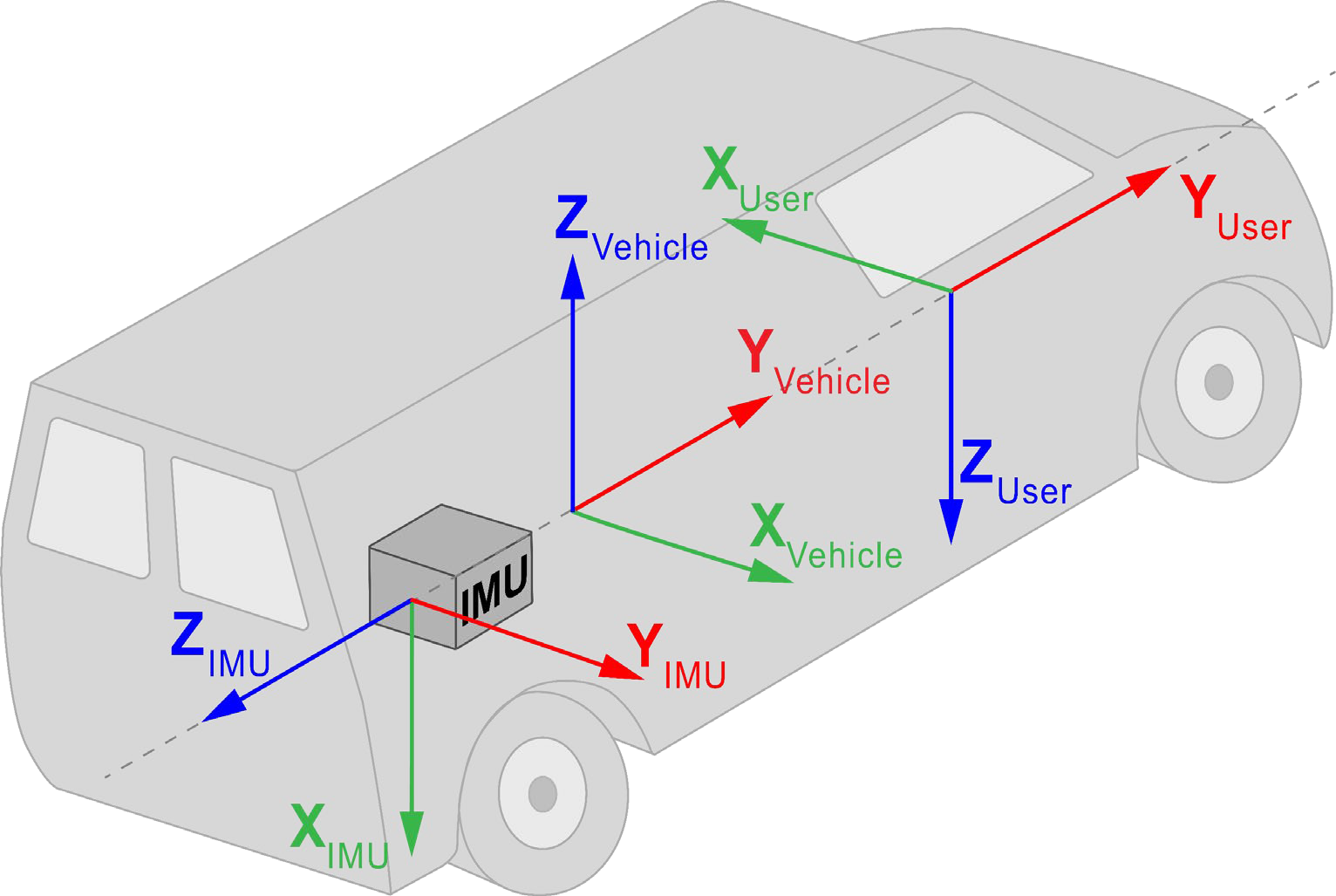
Example for manual configuration using Figure: IMU, vehicle and user rotation example:
SETINSROTATION RBV -90 0 90 3 3 3
Optional Custom User Configurations
User Translation
By default, INS position and velocity solution outputs at the IMU center of navigation. USER translation will translate the INS solution from the IMU center of navigation to another desired external location. To specify the offset between the IMU center of navigation and desired external location, the SETINSTRANSLATION USER command is used.
Example for manual configuration:
SETINSTRANSLATION USER 0.70 -1.20 0.60 0 0 0 IMUBODY (translates INS solution output to antenna phase center)
User Rotation
By default, INS attitude solution outputs in the Vehicle Frame. If INS attitude solution is desired in a different reference frame than the Vehicle Frame, USER rotation will define rotation from IMU Body Frame to the desired reference frame and enable INS attitude output in the desired reference frame. Roll, pitch, and azimuth will output with respect to the Y axis rotation, X axis rotation, and Y axis direction of the desired reference frame. To specify rotation from IMU Body Frame to the desired reference frame, the SETINSROTATION USER command is used.
Example for manual configuration using Figure: IMU, vehicle and user rotation example:
SETINSROTATION USER -90 0 -90
INS Profile
INS Profiles customize some internal configuration ideal for a particular environment, including enhancing performance. Profiles currently available include:
-
DEFAULT – default SPAN profile
-
LAND – fixed axle land vehicle profile
-
MARINE – marine vessel profile
-
FIXEDWING – fixed wing aircraft profile
-
FOOT – walking or backpack application
-
VTOL – vertical take off and landing aircraft profile
-
RAIL – railway profile
-
AGRICULTURE – agriculture application profile
To specify a profile for a SPAN system, send the SETINSPROFILE command at startup. For example:
SETINSPROFILE LAND
Additional Options
ALIGN – NovAtel’s dual antenna ALIGN heading technology can be used to assist the initial alignment of the SPAN solution and provide additional heading updates to the INS filter (very useful for, quick initialization requirements and/or slow/minimal rotation dynamic applications.
Relative INS – supports INS application where position, velocity and attitude vector between two SPAN systems is required.
Heave – supports short term vertical displacement of a vessel relative to the mean sea state caused by waves or swells.
Variable Lever Arm – supports INS application rigidly fixed on a gimballed mount.
-
When using this feature, translation from IMU center of navigation to gimbal and rotation from the IMU body frame to the gimbal mount body frame need to be configured using SETINSTRANSLATION GIMBAL and SETINSROTATION RBM respectively.
INS Initialization
Initialization is the first and most important step of all SPAN system’s real time operation; the effectiveness of this stage can have lasting impacts on the performance throughout operation. Initialization means telling the IMU where it is on the surface of the earth, and how it is oriented so that the IMU errors can be observed and accurately estimated. Initialization can be broken down into two phases, the alignment phase and the convergence phase.
INS Initialization Environment
The following should be followed to have a good INS initialization:
-
Ensure the IMU and antenna (or antennas) are rigidly mounted to the vehicle. The GNSS signal is received at the antenna phase center whereas the IMU raw data and INS solution is computed at the IMU center of navigation. The separation between IMU and antenna must therefore be constant.
-
If using a dual-antenna setup, we recommend having both antennas at constant heights, especially in applications where large pitch/roll will be experienced. Mount the IMU as close as possible to the primary antenna to maximize accuracies.
-
Mount the IMU as far as possible from external sources of vibration.
-
If INS performance is being hindered by vehicle vibrations, consider using dampening mounts to minimize vibrations. Use dampening mounts with caution as there is always a risk of removing actual motion.
-
Measure the lever arm as accurately as possible, and to a better accuracy than that of the GNSS position type accuracy (RTK, PPP, Single Point, etc.), see Lever Arm Calibration Routine or SPAN Translational Offsets for more details.
-
Ensure the antenna has clear visibility of the sky as possible.
-
If using a dual antenna setup, ensure both antennas are far from any obstructions. The GNSS-derived heading must be verified to RTK quality levels before it is fed into the INS. Being close to obstructions lengthens this process or in some cases even prevents the update from taking place.
-
If possible, start logging data as soon as possible so that complete information on INS alignment is saved.
INS Alignment Phase
The alignment phase is the first part of inertial initialization and is defined as the process in which the orientation of the IMU axes are determined in relation to the local level reference frame.
INS alignment methods used to initialize the SPAN INS system can be configured using the ALIGNMENTMODE command. The default ALIGNMENTMODE is AUTOMATIC. In this mode, the first available method to align is used. Sending the ALIGNMENTMODE command manually overrides the AUTOMATIC setting and changes the options available to complete an alignment.
Alignment using manual command and INS seed do not require any specific ALIGNMENTMODE configuration.
-
Static Coarse Alignment – Gyro compassing is used to determine North using only IMU measurements while stationary, no other information is required. It requires IMUs that can gyro compass (typically IMU Grade 2+). This means the IMU can sense the Earth’s rotation rate, SPAN will average the IMU raw measurements for approximately 30 - 45 seconds to acquire the initial pitch, roll and azimuth estimates.
This alignment method is enabled by:
-
ALIGNMENTMODE UNAIDED
-
ALIGNMENTMODE STATIC
-
ALIGNMENTMODE AUTOMATIC
-
-
Kinematic GNSS course over ground – North is defined by the GNSS course over ground and the IMU orientation is initialized based on the GNSS course over ground and the known RBV rotation. It must have a correct RBV rotation configured and forward motion in a straight line. Crab angles (typically observed in marine or aerial environments) will induce a bias to the kinematic alignment and should be minimized during the Kinematic Alignment routine. GNSS course over ground for three consecutive seconds is averaged provided the speed is higher than 5 m/s or the user-specified value (through the SETALIGNMENTVEL command).
This alignment method is enabled by:
-
ALIGNMENTMODE UNAIDED
-
ALIGNMENTMODE KINEMATIC
-
ALIGNMENTMODE AUTOMATIC
-
-
Dual antenna (‘Aided Transfer’) – In this case, the IMU orientation is initialized based on the computed ALIGN heading values and the known rotation between the ALIGN baseline and the IMU frame. Crab angles are no longer an issue. It requires correct ALIGN rotation configuration (ALIGN rotation is automatically calculated using primary and secondary lever arm or defined by the SETINSROTATION ALIGN command; however, it can be further calibrated using the INSCALIBRATE command).
This alignment method is enabled by:
-
ALIGNMENTMODE AIDED_TRANSFER
-
ALIGNMENTMODE AUTOMATIC
-
-
Manual command – SETINITAZIMUTH or EXTERNALPVAS commands. The user or external system is responsible for correctly supplying an initial estimate for the azimuth and appropriate confidence values. Please note this command is meant for bench test purposes OR advanced users. The initial value and its corresponding standard deviation are very important for a proper INS initialization. Using either of these commands with incorrect values and/or standard deviations (e.g., actual value has an error of 30 degrees, but user inputs a standard deviation of 1 degree) has grave repercussions on INS filter performance.
-
INS Seed – Saved and re-validated azimuths from prior operation (requires vehicle to have not moved). The IMU orientation is initialized with the orientation saved at last power off.
Convergence Phase
|
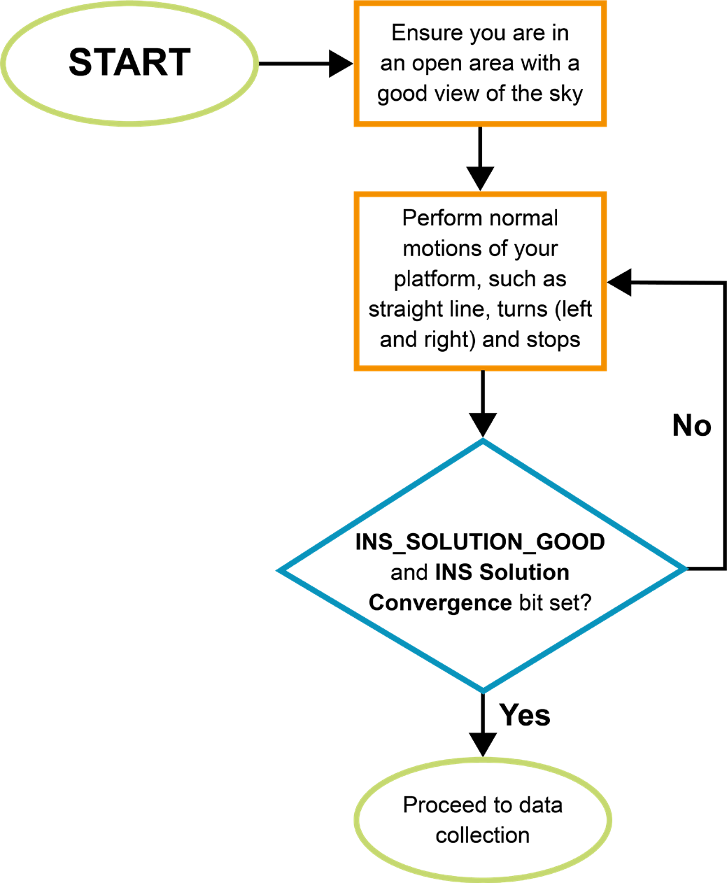
INS alignment procedure
|
As previously mentioned, it is very important to ensure INS alignment takes place in a relatively good GNSS environment. Right after initial INS alignment, it is necessary to insert the appropriate type of kinematics into the system to converge the bias-drift states being modeled. It is suggested to perform the following iterative process, which could take up to three minutes depending on the dynamics the platform is capable of. During this period the INS status should transition to INS_SOLUTION_GOOD and the INS Solution Convergence bit (bit 6) should update to set in the Extended Solution Status of INSPVAX log. INS filter confidence can be monitored through the INS standard deviations in the INSPVAX log. Initializing the INS and entering an urban canyon immediately after is not recommended. SPAN will not behave as per product sheet levels unless it has been properly initiated and this includes the initial kinematics. If possible, start logging data from the very beginning to ensure all information is captured should there be any issues. |
Recommended Messages to be Logged
Although every customer has a different application and setup, it is important to always log as much information about the GNSS and INS filters and the environment in which the survey is taking place. The suggested messages in Recommended Messages to be Logged should be logged for every survey. Note that the list includes all necessary messages for post-processing in Inertial Explorer.
APN-080: SPAN Data Collection Recommendations