Mount the CPT7
Mount the CPT7 in a fixed location where the distance from the CPT7 to the phase center of the GNSS antennas is constant. Ensure that the orientation with respect to the vehicle and antennas is also constant.
The CPT7 enclosure must be grounded.
To ground the CPT7, mount the enclosure to a grounded metal mounting plate or attach a chassis ground cable under one of the mounting screw heads.
Do not install the CPT7 near a heat source, such as vehicle exhaust.
If the CPT7 will be used in an area with a high ambient temperature, above +60°C, and/or additional features have been activated (more channels, HDR mode, etc.), it is strongly recommended to mount the CPT7 to a metal surface such as the NovAtel mount adapter or the metal vehicle chassis. This will improve heat conduction from the unit, optimizing the performance and reducing the risk of a high temperature warning or shutdown.
For the simplest configuration, align the connectors of the CPT7 with the direction of travel of the vehicle and mount the base facing down (see Figure: Default RBV configuration) This coincides with X-axis forward and Z-axis down, and the default RBV configuration is valid. Any other mounting requires a rotational offset to be applied. See Rotational offsets for more information.
The X, Y and Z axis are marked on the CPT7 enclosure.
The default RBV configuration is SETINSROTATION RBV 180 0 90 3 3 3.
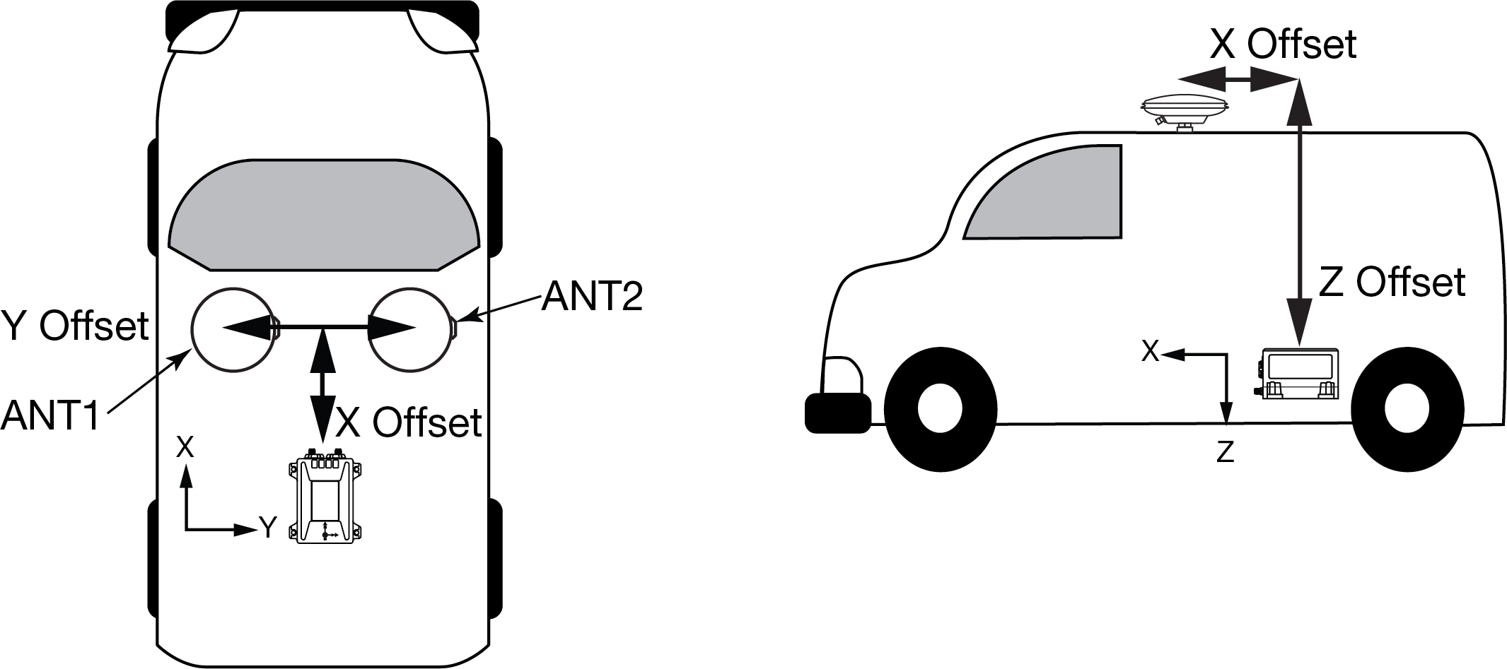
Also, it is important to measure the distance from the CPT7 to the primary and secondary GNSS antennas (the Antenna Lever Arms), on the first usage, on the axis defined on the CPT7 enclosure. See also CPT7 mechanical specifications for dimensional drawings of the CPT7.
Ensure the CPT7 cannot move due to dynamics and that the distance and relative direction between the CPT7 and both antennas is fixed. See SPAN configuration for CPT7.
The closer the primary antenna is to the CPT7, particularly in the horizontal plane, the more accurate the position solution.
Also, your measurements entered using the SETINSTRANSLATION command must be as accurate as possible, or at least more accurate than the GNSS positions being used. For example, a 10 cm error in recording the antenna offset will result in at least a 10 cm error in the output. Millimetre accuracy is preferred.
The offset from the CPT7 to the antennas, and/or a user point device, must remain constant especially for RTK or DGNSS data. Ensure the CPT7, antenna and user point device are bolted in one position perhaps by using a custom bracket.
Securing the CPT7
The CPT7 can be secured directly to the mounting surface or can be secured using the CPT7 Adapter Plate (01020112).
To secure the CPT7 directly to the mounting surface, use four #6 screws that pass through the mounting holes in the CPT7 and into the mounting surface. For the location and spacing of the mounting holes, refer to the mechanical drawings in CPT7 mechanical specifications.
The mounting screws should be torqued to 8 to 10 in-lbs (0.9 to 1.1 N·m).
For information about securing the CPT7 using the adapter plate, refer to Secure the CPT7 using the adapter plate.