SPAN configuration for CPT7
|
Platform: |
CPT7, CPT7700 |
Minimum recommended configuration
When configuring your CPT7 system for first time use, the following is the minimum amount of information required to ensure proper operation of a SPAN system.
|
Required information |
Required command |
|---|---|
|
IMU to primary antenna lever arm |
SETINSTRANSLATION ANT1 |
|
IMU to secondary antenna lever arm (CPT7 only) |
SETINSTRANSLATION ANT2 |
|
IMU to vehicle frame rotation |
SETINSROTATION RBV |
For optimal SPAN operation, the IMU to antenna lever arms and the IMU to vehicle frame rotation should be measured or calibrated to the best accuracy possible. Even small errors in the lever arm or RBV can lead to significant degradation of the overall INS performance.
While this is the minimum amount of information required, additional information is typically needed for SPAN systems. The following commands are commonly used to configure SPAN systems.
|
Common user settings |
Appropriate command |
Notes |
|---|---|---|
|
IMU to output position offset |
SETINSTRANSLATION USER |
Default output position is at the IMU centre |
|
IMU to output frame rotation |
SETINSROTATION USER |
Default output frame is the vehicle frame as defined by SETINSROTATION RBV input |
|
Vehicle type |
|
|
|
Minimum alignment velocity |
|
Configure SPAN manually
Follow these steps to enable INS as part of the CPT7 system using software commands:
A GNSS antenna with a clear view of the sky must be connected and tracking satellites for operation.
-
Issue the SETINSTRANSLATION command, using the ANT1 parameter, to enter the distance from the CPT7 to the primary GNSS antenna.
Issue the SETINSTRANSLATION command, using the ANT2 parameter, to enter the distance from the CPT7 to the secondary GNSS antenna (CPT7 only).
See the SETINSTRANSLATION command for more information.
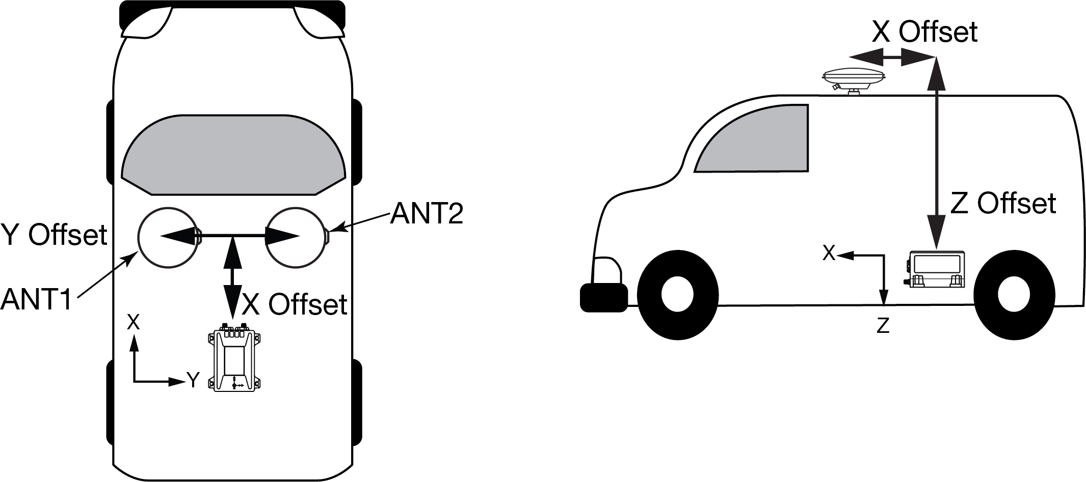
The offset between the antenna phase centre and the IMU axis must remain constant and be known accurately (m). The X, Y and Z directions are clearly marked on the CPT7 enclosure. The SETINSTRANSLATION parameters are (where the standard deviation fields are optional and the distances are measured from the CPT7 to the antenna):
ANT1 x_offset y_offset z_offset [x_stdev] [y_stdev] [z_stdev]
ANT2 x_offset y_offset z_offset [x_stdev] [y_stdev] [z_stdev]For example, in the following scenario:
-
the CPT7 is mounted on the floor in the orientation described in Mount the CPT7 (positive Z down, positive X forward)
-
the primary and secondary GNSS antennas are mounted on the roof of the vehicle
-
the distance measured from the CPT7 to the primary GNSS antenna is 2 metres up (Z axis), 0.5 metres right (Y axis) and 1 metre forward (X axis)
the distance measured from the CPT7 to the secondary GNSS antenna is 2 metres up (Z axis), 0.5 metres left (Y axis) and 1 metre forward (X axis)
the SETINSTRANSLATION commands would be:
SETINSTRANSLATION ANT1 1.0 -0.5 -2.0
SETINSTRANSLATION ANT2 1.0 0.5 -2.0
CPT7 to antenna offset
The axis marking on the CPT7 indicates the orientation of the X, Y and Z axis only. It does not indicate the centre of navigation. For the location of the centre of navigation, refer to Figure: CPT7/CPT7700 centre of navigation.
A typical RTK GNSS solution is accurate to a few centimetres. For the integrated GNSS+INS system to have this level of accuracy, the offset must be measured to within a centimetre. Any offset error between the two systems shows up directly in the output position. For example, a 10 cm error in recording this offset will result in at least a 10 cm error in the output.
-
-
Issue the SETINSROTATION command, using the RBV parameter, to enter the Euler Angle rotation from the IMU Body frame to the Vehicle frame. See the SETINSROTATION command for more information.
Accurate knowledge of the rotational offset between the IMU Body frame and the Vehicle frame (the RBV rotation) is critical to correctly computing an attitude solution, and is required before a Kinematic alignment is possible.
The SETINSROTATION parameters are (where the standard deviation fields are optional):
RBV x_rotation y_rotation z_rotation [x_stdev] [y_stddev] [z_stdev]
The order of rotations is Z-X-Y. All rotations are right handed.
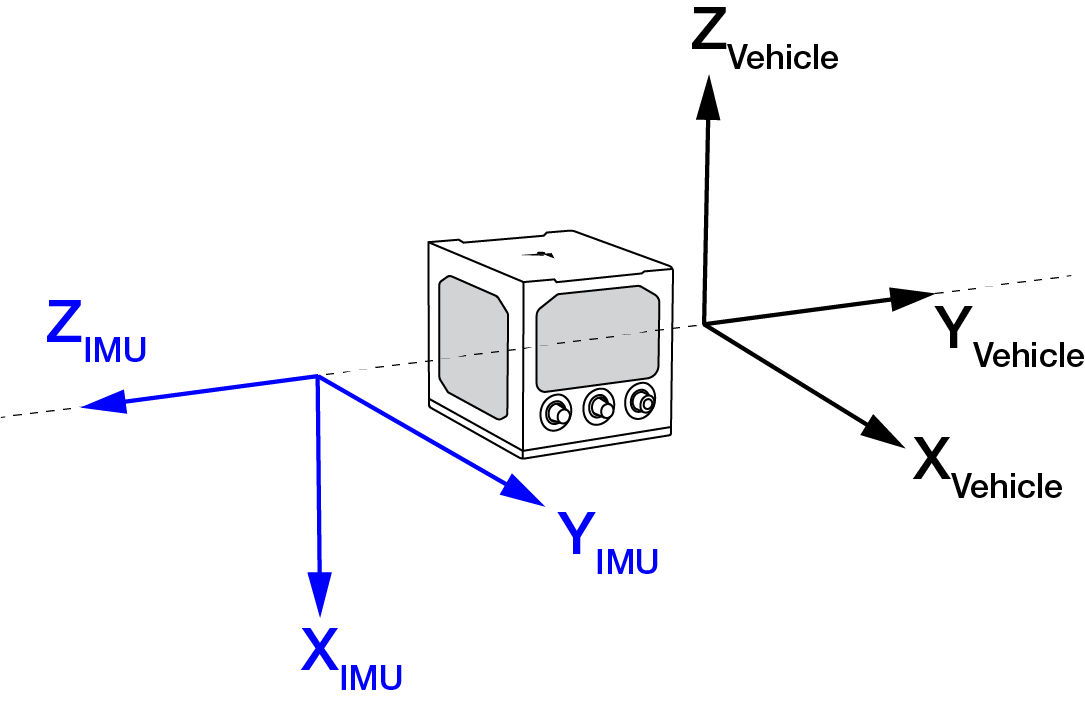
For an example of how to solve for the IMU Body to Vehicle frame rotation refer to Rotational offsets.
If the rotation between the IMU Body frame and the Vehicle frame is not precisely known, enter an approximate rotation (to the nearest 45 degrees). The precise offset can be estimated by carrying out the Body to vehicle frame rotation calibration routine.
SPAN configuration with NovAtel Application Suite
NovAtel Application Suite provides a graphical user interface to help configure a SPAN system. For information about configuring SPAN using NovAtel Application Suite, refer to docs.novatel.com/Tools/Content/ToolsSuite/Overview.htm.
SPAN configuration with NovAtel Manage Web
The SPAN parameters can be configured using the NovAtel Manage Web User Interface. For information about using Manage Web, refer to docs.novatel.com/Tools/Content/Manage_Web/Overview.htm.