SPAN translations and rotations
|
Platform: |
OEM719, OEM729, OEM7500, OEM7600, OEM7700, OEM7720, PwrPak7, CPT7, CPT7700 |
A SPAN system combines GNSS and INS into a single system. In a GNSS system, the position is reported relative to the phase centre of the GNSS antenna. In an INS system, the position, velocity and attitude data is reported relative to the centre of navigation of the IMU. For a SPAN system to provide a combined GNSS+INS position, velocity and attitude, it must know where the GNSS antenna is positioned relative to the IMU.
The orientation of the IMU relative to the forward direction of the vehicle is also needed to convert the velocity and attitude changes sensed by the IMU into the actual motion of the vehicle.
If the SPAN system incorporates other devices, such as a camera connected to an Event Input, the SPAN system also needs to know the location and orientation of these additional devices relative to the IMU.
Translational offsets
The three dimensional distances between the IMU and other SPAN components are called translational offsets.
The translational offsets are measured in three directions, X axis, Y axis and Z axis, typically relative to the IMU Body frame. Translational offsets can also be entered relative to the Vehicle frame.
The X, Y and Z axes of the IMU Body frame are typically indicated on the IMU enclosure.
The X, Y and Z axes of the IMU Body frame are also indicated on the mechanical drawings of the IMUs in the
Figure: IMU to antenna translation offset shows an example of the translational offsets from the IMU to a GNSS antenna. In this example, the IMU Body Frame (indicated by the small arrows) has the Y axis pointing in the direction of the vehicle motion and the z axis pointing up.
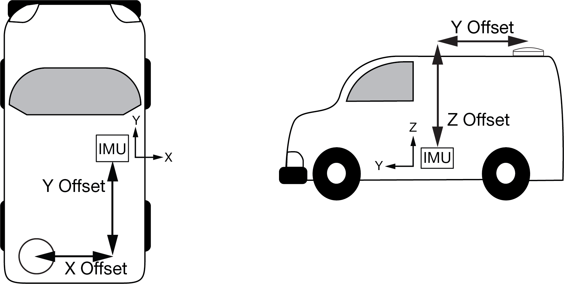
If the distances measured in this example were X Offset = 1.000 m, Y Offset = 1.500 m and Z Offset = 2.000 m, the following values would be entered, based on the IMU Body Frame:
-
x = -1.000
-
y = -1.500
-
z = 2.000
The translational offsets are entered using the SETINSTRANSLATION command. For this example, the command to enter these offsets is:
SETINSTRANSLATION ANT1 -1 -1.5 2
The measurements for the translational offsets should be done as accurately as possible, preferably to within millimetres especially for RTK operation. Any error in the offsets will translate into an error in the INS position.
The translational offsets from the IMU to the GNSS antenna are required for all SPAN systems. However, some SPAN systems may have other sensors or devices integrated into the system for which the SPAN needs translational offsets. For example, a gimbal mount or a camera or LiDAR connected to an Event Input line. The offsets to these additional sensors and devices are also entered using the SETINSTRANSLATION command.
By default, the translational offsets are entered in the IMU Body Frame. However, in some systems the IMU Body Frame may not be known precisely. For these cases, the SETINSTRANSLATION command has an option that allows the offsets to be entered relative to the Vehicle Frame. In these cases, the rotation from the IMU Body Frame to the Vehicle Frame (RBV) is used to rotate offsets into the default IMU Body frame as required. To achieve the best results, this means that the RBV rotation must be known very precisely. Typically this is achieved through the SPAN RBV Calibration procedure. See Body to vehicle frame rotation calibration routine or Multi-line body to vehicle frame rotation calibration routine for information about this calibration procedure.
Rotational offsets
The differences in orientation between the IMU and other SPAN components are called rotational offsets. Rotational offsets are given as the rotation from the IMU Body Frame to the frame of interest.
The order of rotations is Z-X-Y and all rotations are right handed.
Generally, frames of reference are defined as Z up, with Y forward, and X completing the right-handed system. An example is the vehicle frame, where Z is always considered to be upwards, Y forward through the direction of travel, and X to the right.
Rotational offsets – example
Consider an IMU installed in the following way:
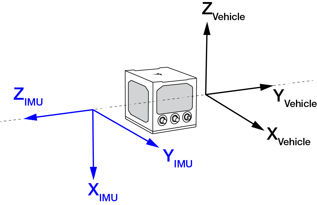
Here, the Euler Angles to rotate from the IMU Body frame to the Vehicle frame (RBV) are:
-
X: -90
-
Y: 0
-
Z: +90
To reach this answer, keep in mind the following rules:
-
The goal is to rotate the IMU Body frame to be coincident with the Vehicle frame (i.e. IMU X equals Vehicle X, IMU Y equals Vehicle Y, IMU Z equals Vehicle Z).
-
You must rotate from the IMU Body frame to the Vehicle frame.
-
You must rotate in the order Z, X, Y.
-
Positive rotation is defined according to the right hand rule.
Z rotation:
Observe that if a positive 90 degree rotation is performed about the IMU Z axis, the rotated IMU X axis becomes collinear with the Vehicle X axis.
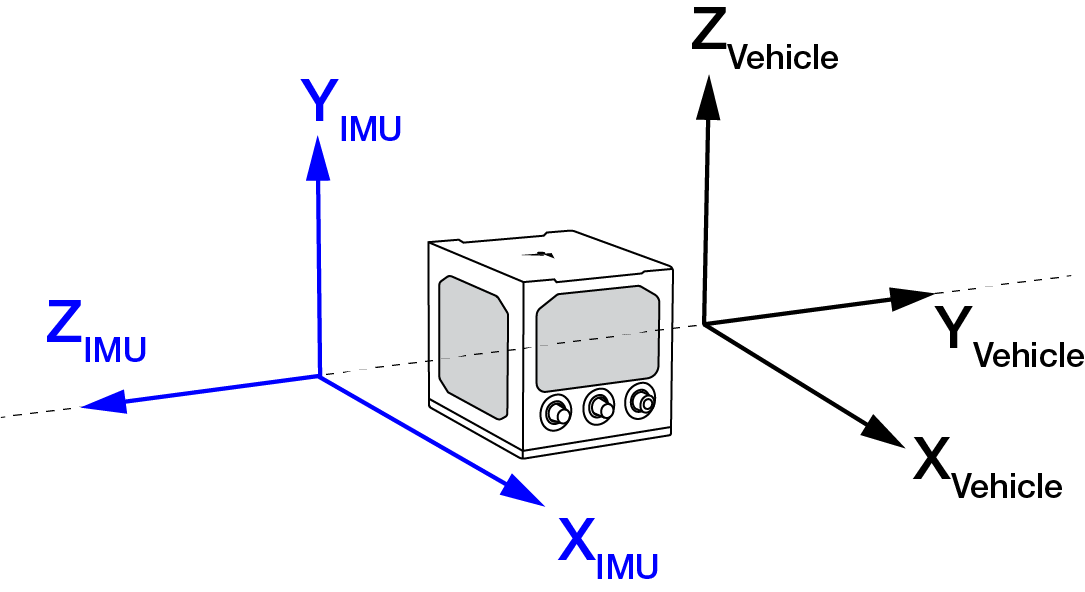
X rotation:
Observe that if a negative 90 degree rotation is performed about the new IMU X axis, the rotated IMU Y axis is now collinear with the Vehicle Y axis, and the rotated IMU Z axis is also collinear with the Vehicle Z axis.
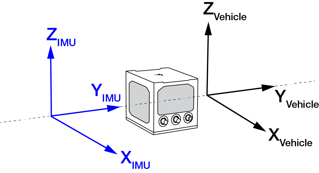
Y rotation:
Since all three sets of axes are already collinear, our frames are coincident, and no further rotation is required.
This solution is not unique. Due to the properties of Euler Angles, there are usually multiple sets of equivalent rotations.
The rotational offsets are entered using the SETINSROTATION command. For this example, the command to enter the rotations for the previous example is:
SETINSROTATION RBV -90 0 90
Output location for logs
The following table lists the output location and frames for OEM7 logs.
|
Log |
Default (position / velocity / heave) output location |
Translation offset options (position / velocity / heave) SETINSTRANSLATION |
Rotational offset options (attitude) SETINSROTATION |
Attitude reference frame |
|---|---|---|---|---|
|
IMU centre of navigation |
N/A |
USER > RBV |
IMU Body (default) → Vehicle (RBV) → Custom user (USER) |
|
|
IMU centre of navigation |
USER |
N/A |
N/A |
|
|
IMU centre of navigation |
USER |
USER > RBV |
IMU Body (default) → Vehicle (RBV) → Custom user (USER) |
|
|
IMU centre of navigation |
USER |
N/A |
N/A |
|
|
IMU centre of navigation |
USER |
USER > RBV |
IMU Body (default) → Vehicle (RBV) → Custom user (USER) |
|
|
IMU centre of navigation |
N/A |
USER > RBV |
IMU Body (default) → Vehicle (RBV) → Custom user (USER) |
|
|
IMU centre of navigation |
USER |
N/A |
N/A |
|
|
IMU centre of navigation |
USER |
USER > RBV |
IMU Body (default) → Vehicle (RBV) → Custom user (USER) |
|
|
IMU centre of navigation |
USER |
N/A |
N/A |
|
|
IMU centre of navigation |
USER |
N/A |
N/A |
|
|
IMU centre of navigation |
USER |
USER > RBV |
IMU Body → Vehicle (RBV) → Custom user (USER) |
|
|
MARK1PVA |
IMU centre of navigation |
MARK1 |
MARK1 |
IMU Body (default) → Custom mark (MARK1) |
|
MARK2PVA |
IMU centre of navigation |
MARK2 |
MARK2 |
IMU Body (default) → Custom mark (MARK2) |
|
MARK3PVA |
IMU centre of navigation |
MARK3 |
MARK3 |
IMU Body (default) → Custom mark (MARK3) |
|
MARK4PVA |
IMU centre of navigation |
MARK4 |
MARK4 |
IMU Body (default) → Custom mark (MARK4) |
|
IMU centre of navigation |
USER |
USER > RBV |
IMU Body (default) → Vehicle (RBV) → Custom user (USER) |
|
|
IMU centre of navigation |
N/A |
N/A |
IMU Body |
|
|
IMU centre of navigation |
USER |
N/A |
N/A |
|
|
IMU centre of navigation |
USER |
USER > RBV |
IMU Body (default) → Vehicle (RBV) → Custom user (USER) |
|
|
Primary Antenna L1 phase centre |
N/A |
N/A |
N/A |
|
|
Primary Antenna L1 phase centre |
N/A |
N/A |
N/A |
|
|
Primary Antenna L1 phase centre |
N/A |
N/A |
N/A |
|
|
Primary Antenna L1 phase centre |
N/A |
N/A |
N/A |
|
|
Primary Antenna L1 phase centre |
N/A |
N/A |
N/A |
|
|
Primary Antenna L1 phase centre |
N/A |
N/A |
N/A |
|
|
Primary Antenna L1 phase centre |
N/A |
N/A |
N/A |
Priority of the output frame is indicated by the arrow sign (→) when multiple rotation settings have been configured.
Gimbal Locked Mount Frame backs out the INPUTGIMBALANGLE rotation to output INS in the locked frame, i.e. INS output if no gimbal angles were issued.