Preparing the data, signal and power interface
The interface provides connections to some or all of the following:
-
Communication ports, including COM, Ethernet, USB and CAN
-
Input and output timing strobes
-
Power input
-
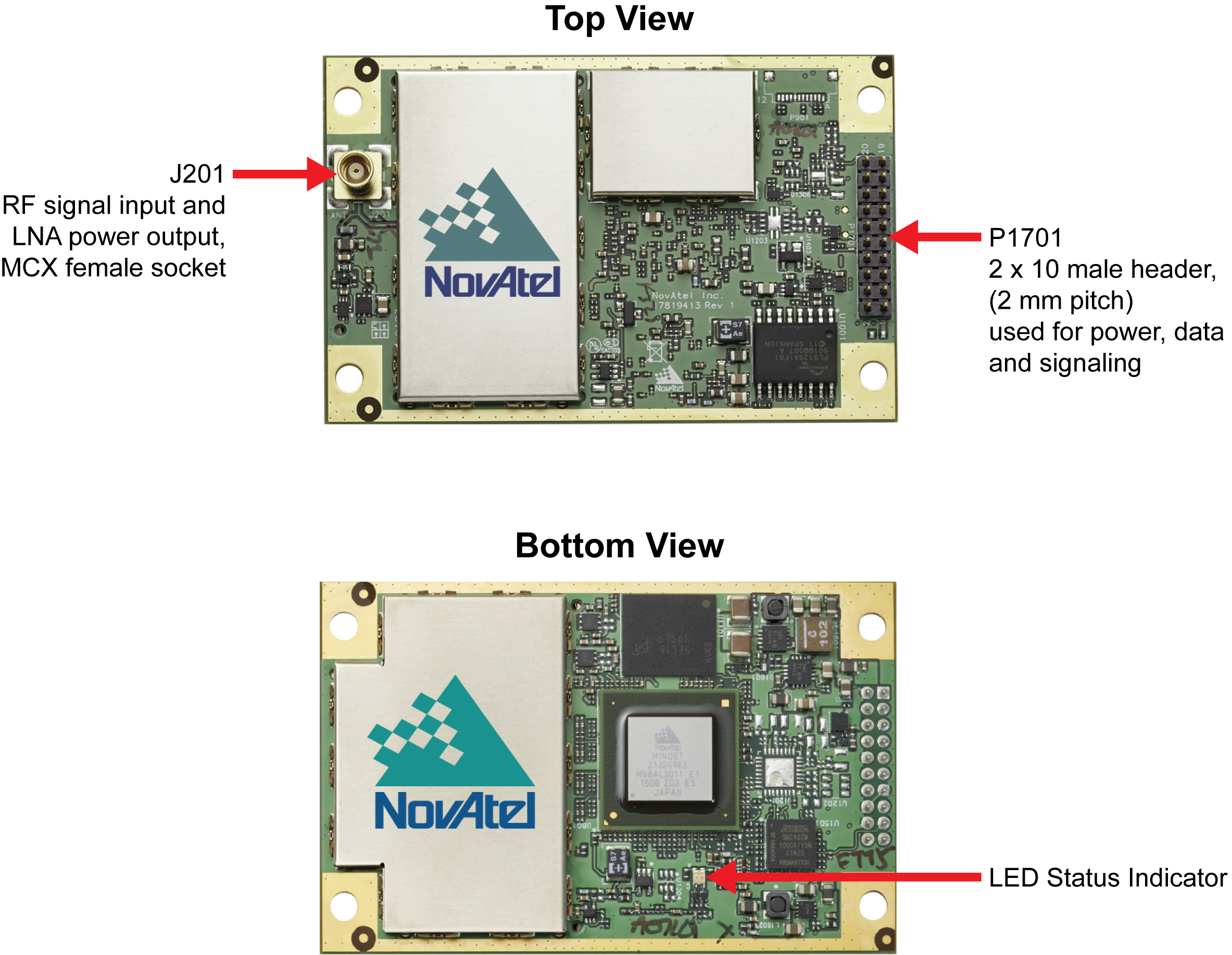
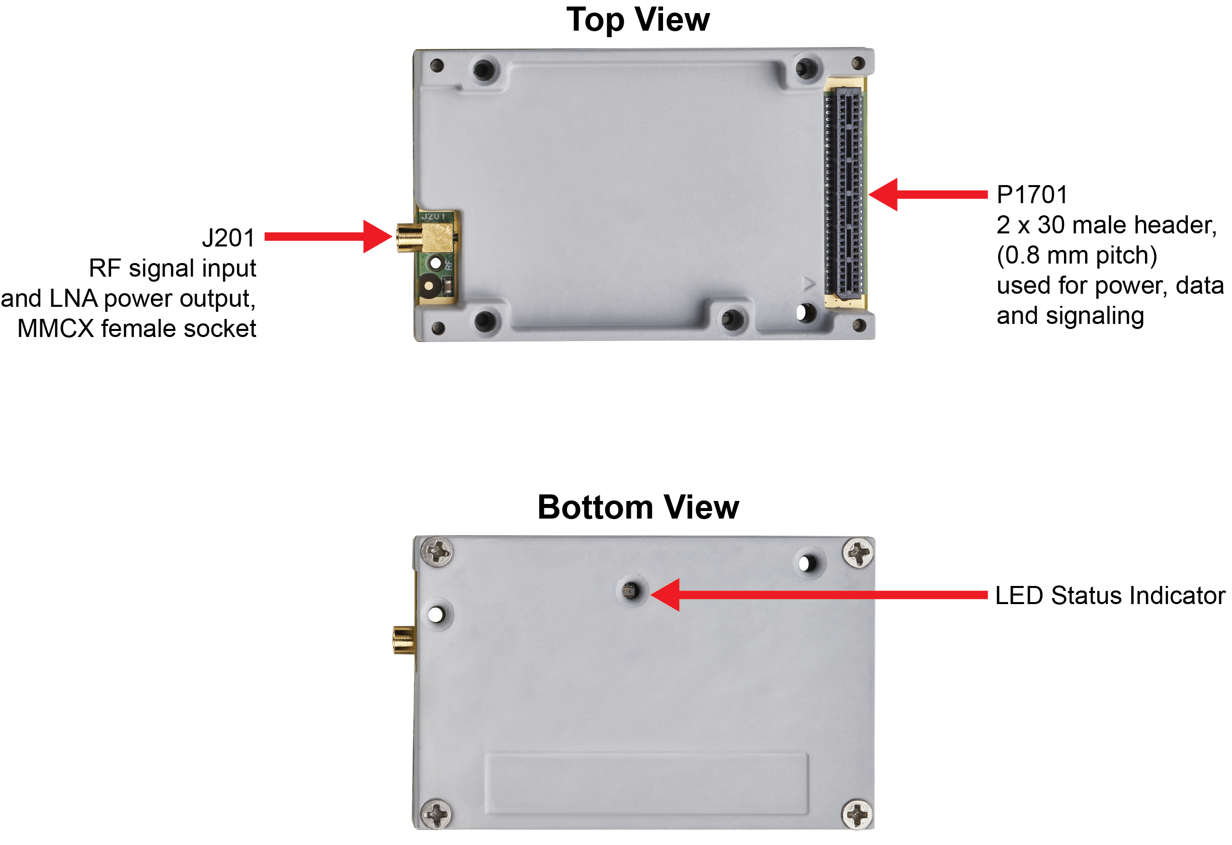
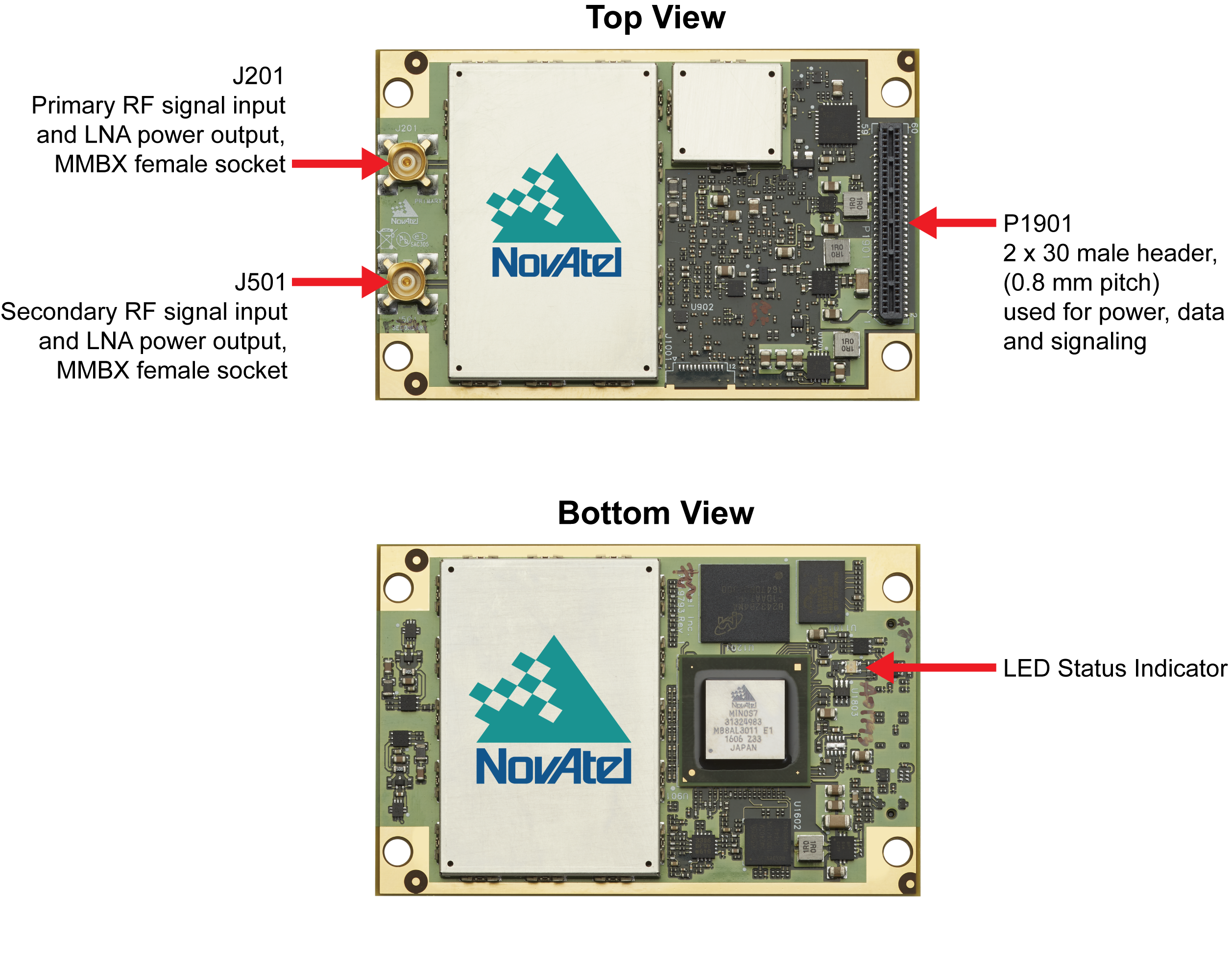
RF signal input
-
Optional external frequency reference
For all OEM7 receiver cards, the power, status and data inputs and outputs are accessed from the interface connector. The interface therefore, must be designed to mate with this connector.


Many of the OEM7 communication and I/O signals are provided at LVCMOS levels and may need interface circuits to communicate with other devices. See Receiver card interface examples for examples of these interface circuits.
The LED status indicator blinks green at approximately once per second to indicate normal operation. If the indicator is red, the receiver is not working properly. The indicator’s operation is described in Built-In Status Tests.