Solve Boresighting Angles
Solving boresighting angles is not supported on GrafNav or GrafNav Static.
Inertial Explorer offers the ability to compute the boresight angle between the IMU and a frame imaging system. We use an external bundle adjustment’s omega, phi and kappa Euler angle values to compute the angular difference between the systems. Once these values have been computed they can then be saved for future projects to use when exporting the omega, phi and kappa values so your trajectory angles are for the camera system. All the boresight related data will be saved in an ASCII BSI file which should not need to be modified.
What You Need to Get Started
-
A data set flown over a targeted calibration field with four flight lines in opposing directions (e.g. north, south, east, add west) and four to six photos in each line.
-
Imagery must have 60% overlap along each line (stereo photography is highly desirable) and a minimum of 20% side lap between lines.
-
The imagery must have tie points and a minimum of four control points, although more can be very helpful.
-
Scale is not so important, but should match typical flying scales. Very large scales (<1:8000) may result in less accurate boresighting angles due to increased influence by GNSS positioning errors.
-
GNSS and IMU data that contains camera event marks. Images must have been properly time tagged by the GNSS-IMU system.
-
A GNSS-only processed solution initially.
-
A valid bundle adjustment solution using these tie and control points as well as the GNSS/camera center positions. Although using the GNSS position is not necessary, it is highly suggested to decorrelate the image position and attitude.
-
Exported omega, phi, kappa in a format compatible with this module.
The naming convention used for the photo IDs must match that used in Inertial Explorer.
-
A fully processed Inertial Explorer project with a forward, reverse, combined or smoothed IMU solution loaded.
Refer to Mathematical Equations Used with Boresighting for the mathematical equations used by boresighting.
Show
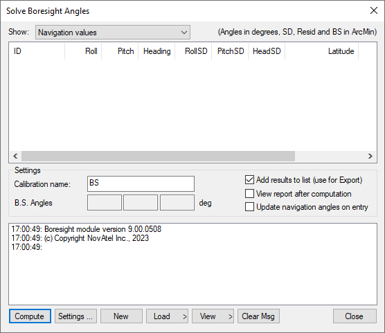
This drop-down menu is linked to the window below it and gives viewing access to the values listed below.
Navigation values
The roll, pitch and heading values, along with their associated standard deviations, are displayed for each loaded camera event. The coordinates of the IMU at the time of the event are also displayed. These values are generally transferred from Inertial Explorer directly and correspond to the IMU values interpolated at camera event times.
Photo E/O values
The omega, phi and kappa values, along with their associated standard deviations, are displayed for each loaded camera event. These values are produced externally in a photogrammetric package.
Matches/residuals
Before the computations begin, choose whether or not to include the observations associated with a camera event in the least squares procedure by right-clicking on the event. After the least squares procedure has finished, the window is updated with the final residual values at each camera event. Additional information, such as quality indicators and computed omega, phi and kappa values are also displayed.
Settings
The following features are available:
Calibration name
Enter a name to distinguish calibration runs from one another. Inertial Explorer keeps a history of calibration runs, so a unique identifier is helpful when trying to recover previous results. This is useful for using multiple systems and/or tracking stability over time.
Boresight Angles
Upon successful completion of the calibration procedure, the final values for the computed boresight angles are displayed here.
Add results to list
When this option is enabled, the last values computed by the program are stored so that they are easily accessible by the Export Wizard.
View report after computation
Enabling this option forces the software to launch the boresighting report upon successful completion of a calibration. The contents of the report are discussed later on.
Update navigation angles on entry
When this option is enabled, Inertial Explorer loads the latest navigation values for the camera events into the boresighting module.
Message Window
This window provides valuable insight on the status of the current calibration. Whenever input data is being loaded, read the messages to ensure the expected number of camera events have been read in. After the calibration procedure is complete, the final boresighting values, as well as the number of iterations needed to arrive at them, are displayed.
The following options are available via the buttons along the bottom of the Solve Boresight Angles window:
Compute
Assuming all the required input data has been loaded, click this button to begin the iterative least squares procedure. The Message Window contains pertinent information regarding the success or failure of the procedure.
Settings…
This button gives access to the Boresight Settings window, which is useful for configuring many parameters used in the boresight calibration. See Boresight Settings for information about the setting on this window.
New
This button clears any stored data from previous calibration runs in order to start a new one.
Load
Use this button to load the required navigation and exterior orientation input data.
The navigation data can be obtained either by loading the latest set of roll, pitch and heading values computed by Inertial Explorer, or by an external file which contains this information for each camera event. Alternatively, if such information is available, there is the ability to provide the module directly with the omega, phi and kappa angles required to rotate the ground system into the IMU frame. Obtaining the attitude angles directly from Inertial Explorer is by far the most common usage.
The exterior orientation parameters for each photo must be supplied by an external file. This file should contain the omega, phi and kappa angles required to rotate the ground system into the image system.
View
This button gives access to the post-calibration report. The report contains relevant boresight calibration information, as well as a list of all the input data provided for each camera event. The bottom of the report displays the boresight values and residuals from the final iteration.
This report can be viewed through either NotePad or the internal Inertial Explorer ASCII viewer. This button also gives you access to the calibration history. For each calibration run, the final boresighting results are saved, assuming the Add results to list option is enabled.
Clear Msg
This button clears the Message Window of any messages currently displayed.