Determining Rotations in SPAN & Inertial Explorer
An important step in both real-time and post-processing projects is to define the rotations between the IMU Frame and another reference frame, such as a vehicle frame. If the rotations are improperly set, or not entered at all, there can be serious consequences, such as a failed kinematic alignment. Both Inertial Explorer (IE) and SPAN use intrinsic ZXY-order Euler angles to define the rotation between the IMU and Target Frames, but each has a slightly different approach to how these rotations are executed. This document outlines how to determine rotation angles in SPAN OEM6, SPAN OEM7, and Inertial Explorer. Flow Charts are included to step through the process of determining the rotation sequence, when looking at the physical setup of the IMU. A section of examples at the end provides an opportunity to practice with rotations and become more familiar with the process.
For those who are both SPAN and Inertial Explorer users, this document should be read in conjunction with the Application Note SPAN Data Logging for Inertial Explorer. This second document outlines how to properly log data with SPAN to auto-fill set up parameters in Inertial Explorer projects. If the IMU orientation is properly determined and logged in the SPAN setup, these values will be automatically converted and entered in the Inertial Explorer project.
Basic Frames and Rotations
The objective of a rotation sequence is to rotate from one reference frame to another. It is important to note that rotations are applied in the order Z X Y, and the rotation sequence is written in the order X Y Z. There are three primary reference frames used in rotations. As shown in Table: Reference Frames, each frame is termed slightly differently in SPAN OEM6, SPAN OEM7, and Inertial Explorer. For the purpose of this document, all examples will refer to the frames as defined in the first column.
The direction in which the rotations are applied is also dependent on the platform:
-
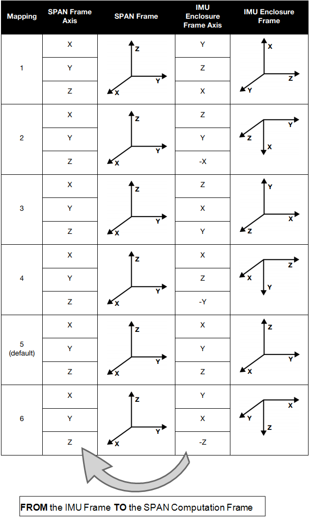
SPAN OEM6: the rotations are applied to the Vehicle Frame to rotate into the SPAN Computation Frame (FROM the Vehicle Frame TO the SPAN Computation Frame). This SPAN Computation Frame is mapped from the IMU frame, by applying a predefined Mapping 1 thru 6 (See Full Mapping Definitions in the SPAN on OEM6 Firmware Reference Manual).
-
SPAN OEM7: the rotations are applied to the IMU Frame to rotate into the Vehicle Frame (FROM the IMU Frame TO the Vehicle Frame).
-
Inertial Explorer: the rotations are applied to the Vehicle Frame to rotate into the IMU Frame (FROM the Vehicle Frame TO the IMU Frame).
The rotation angles are executed in a right hand positive system. This means that rotations in the counter-clockwise direction are positive. To quickly determine if a rotation is positive or negative, point your right-hand thumb in the direction of the axis (vector points outwards from the frame origin), and curl your fingers towards your palm. The direction of your curled fingers shows the positive rotation about the chosen axis.
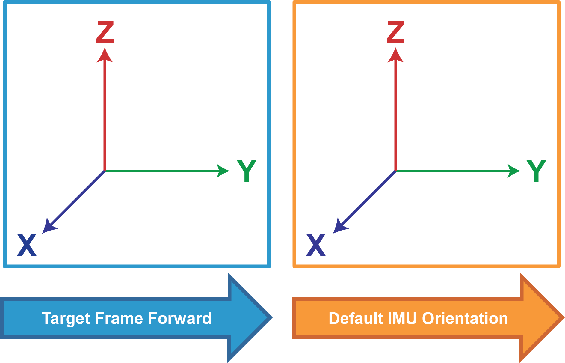
Figure: Standard Target Frame, with Default IMU Setup shows the frame used to define the default or standard setup. The standard Target Frame is set as Y forward, Z up, and X right (completing a right-hand system). A rotation of 0 0 0 is the Default IMU Orientation where the IMU Frame is aligned with this standard Y forward, Z up, X right frame orientation.
Whenever possible, mount the IMU in the Default Orientation such that no rotations need to be applied (Y Forward, Z Up, X Right). This will reduce the possibility of blunders or errors caused by incorrectly configured rotations.
When more than one rotation is applied, there are often multiple ways to define the rotation sequence; but all will lead to the same end result. The flowcharts in the following sections outline one possible approach to determining rotations within each system; however, you may find other sequences as you become more familiar with the process.
SPAN OEM6 Rotations
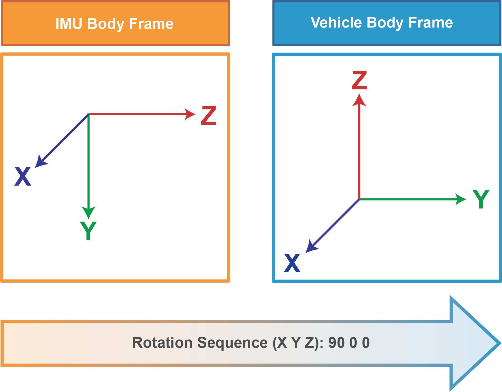
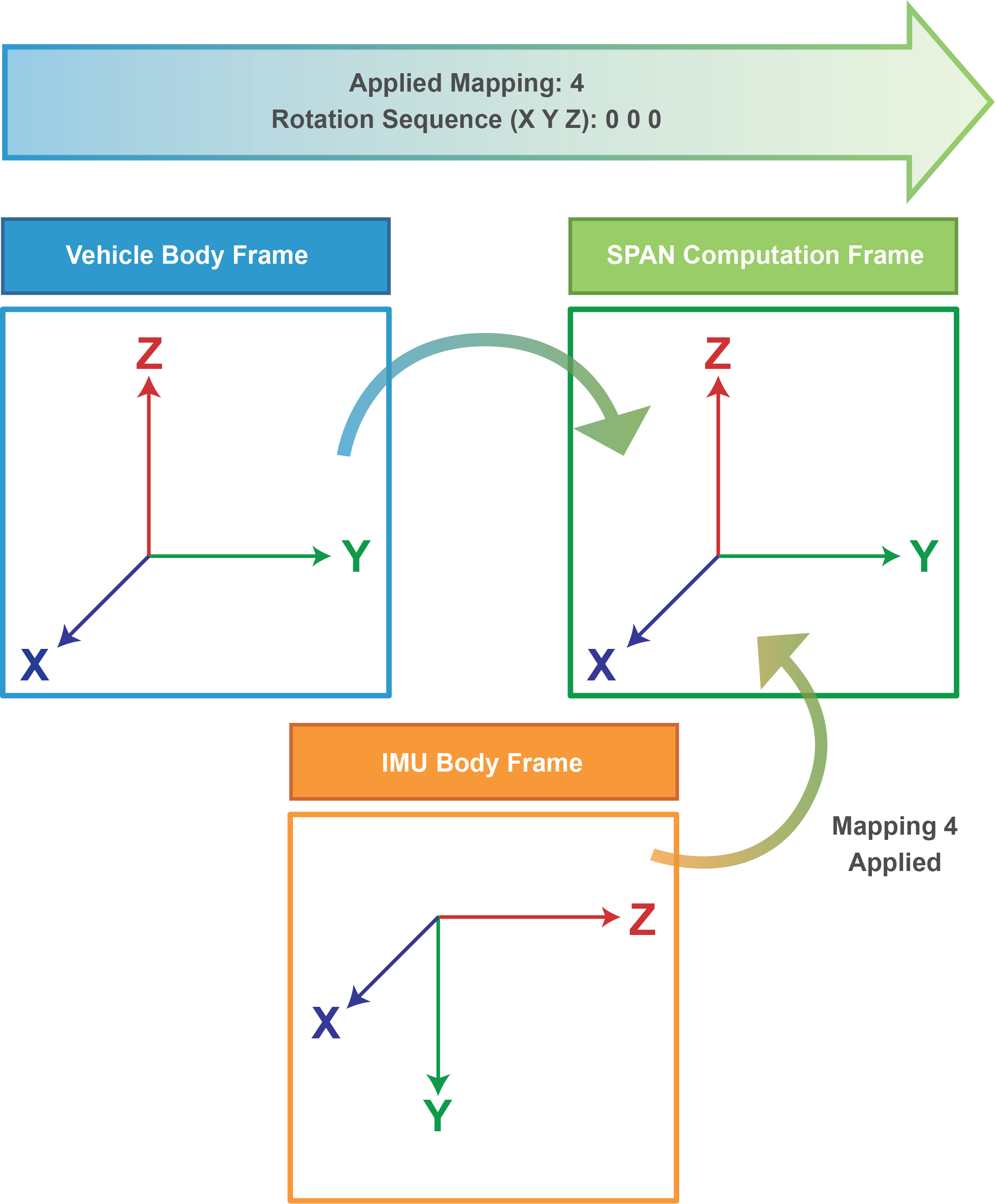
In SPAN OEM6, rotations are FROM the Vehicle Body Frame TO the SPAN Computation Frame, as shown in Figure: SPAN OEM6 Rotations. Rotations from the Vehicle Body Frame are defined by VEHICLEBODYROTATION. The SETIMUORIENTATION command is used to define and apply the Mapping FROM the IMU Body Frame to the SPAN Computation Frame. For more details on these commands please refer to the SPAN on OEM6 Firmware Reference Manual.
FROM the Vehicle Body Frame TO the SPAN Computation Frame.
The IMU Body Frame is mapped into the SPAN Computation Frame
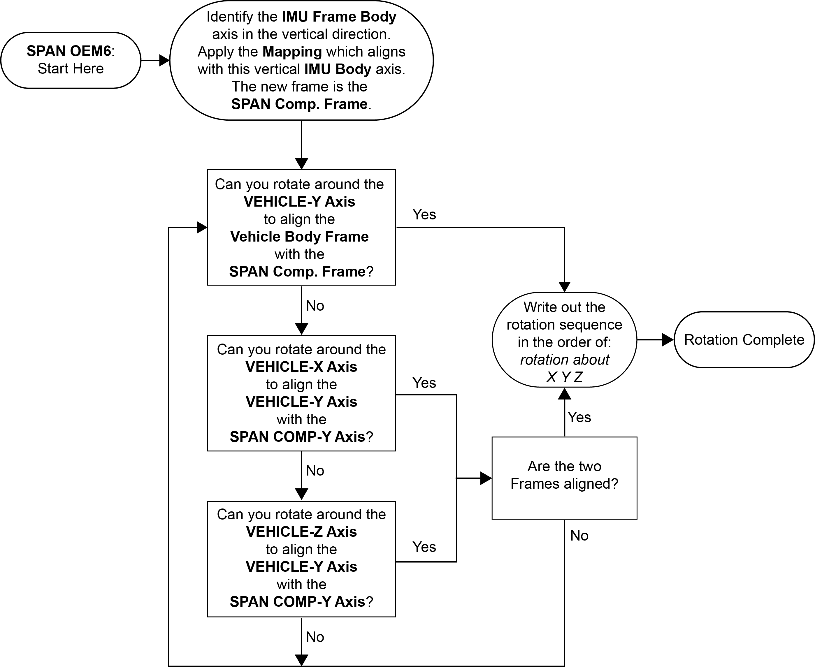
Flow Chart – Determining Rotations in OEM6
Understanding Mappings and the SPAN Computation Frame
OEM6 applications work with three reference frames when defining a rotation sequence: the Vehicle Body Frame, the IMU Body Frame, and SPAN Computation Frame. Both the IMU Body Frame and SPAN Computation Frame are used to define the orientation of the IMU. The IMU Body Frame defines the orientation in physical space, whereas the SPAN Computation Frame defines the orientation for computations, which forces Z to be up.
If the IMU Body frame is not mounted with the Z-axis approximately up (as marked on the enclosure), a new IMU frame is defined, called the SPAN Computation Frame. This SPAN Computation Frame is defined by a Mapping applied to the original IMU Frame. Figure: Full Mapping Definitions lists the possible mappings used for this transformation. The SETIMUORIENTATION command is used to set the mapping definition, before any rotations are applied.
To determine which Mapping to apply, identify the axis in the IMU Body Frame which is most closely aligned with gravity (vertically positioned). Then, use the last column in Figure: Full Mapping Definitions, IMU Enclosure Frame, to look for the SPAN Computation Frame which has this same axis in the vertical direction. For example, the Y axis of the IMU Body Frame in Figure: SPAN OEM6 Rotations is vertically positioned, which means that Mapping 4 should be applied.
When applying the Mapping, it is not necessary to identify, and align with, the forward direction of the Vehicle Body Frame; there may still be a rotation between the SPAN Computation Frame and the Vehicle Body Frame after the Mapping is applied. More information on mappings can be found in the SETIMUORIENTATION command section in the SPAN on OEM6 Firmware Reference Manual.
SPAN OEM7 Rotations
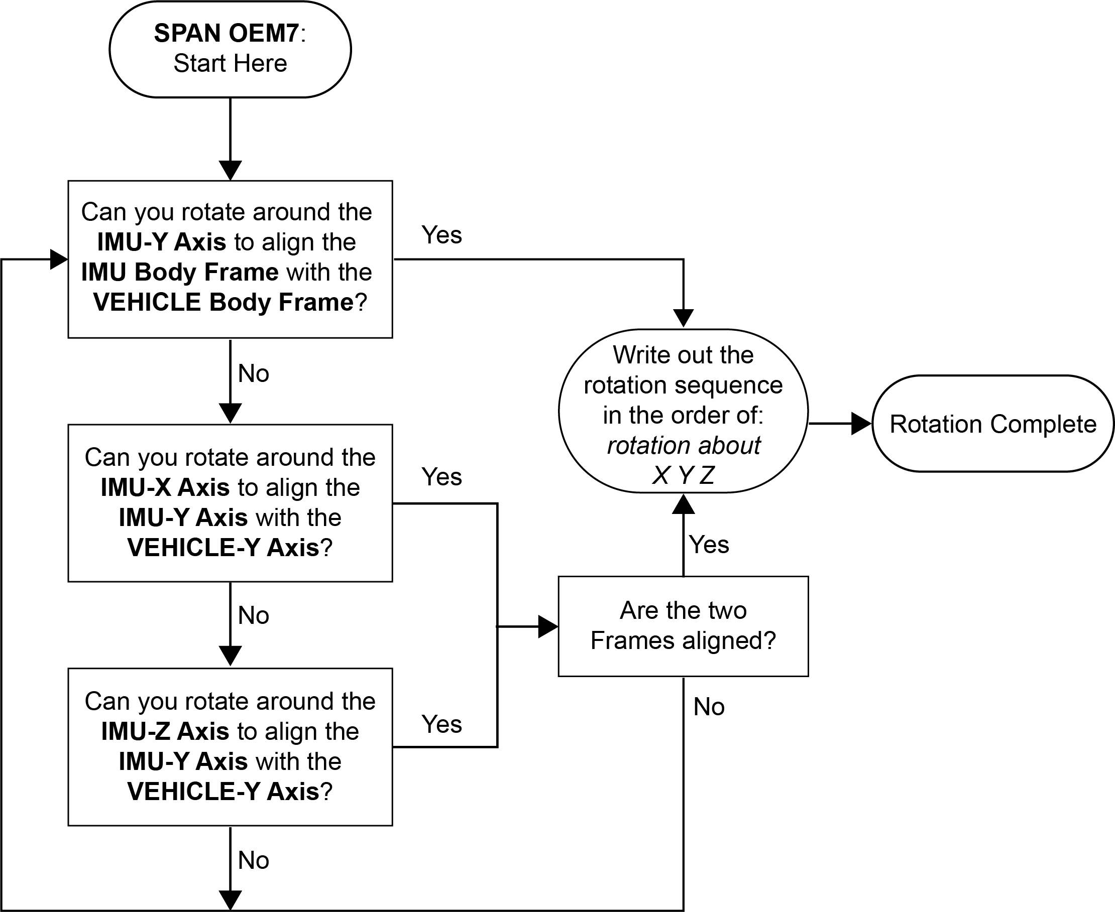
In SPAN OEM7, rotations are FROM the IMU Body Frame TO the Vehicle Body Frame, as shown in Figure: SPAN OEM7 Rotations. Rotations to the Vehicle Body Frame are configured using the SETINSROTATION RBV command. This SETINSROTATION command can also be used to define rotations to other frames within the setup, such as a Gimbal Mount Frame. For details on this command, refer to the
Flow Chart – Determining Rotations in SPAN OEM7
Inertial Explorer Rotations
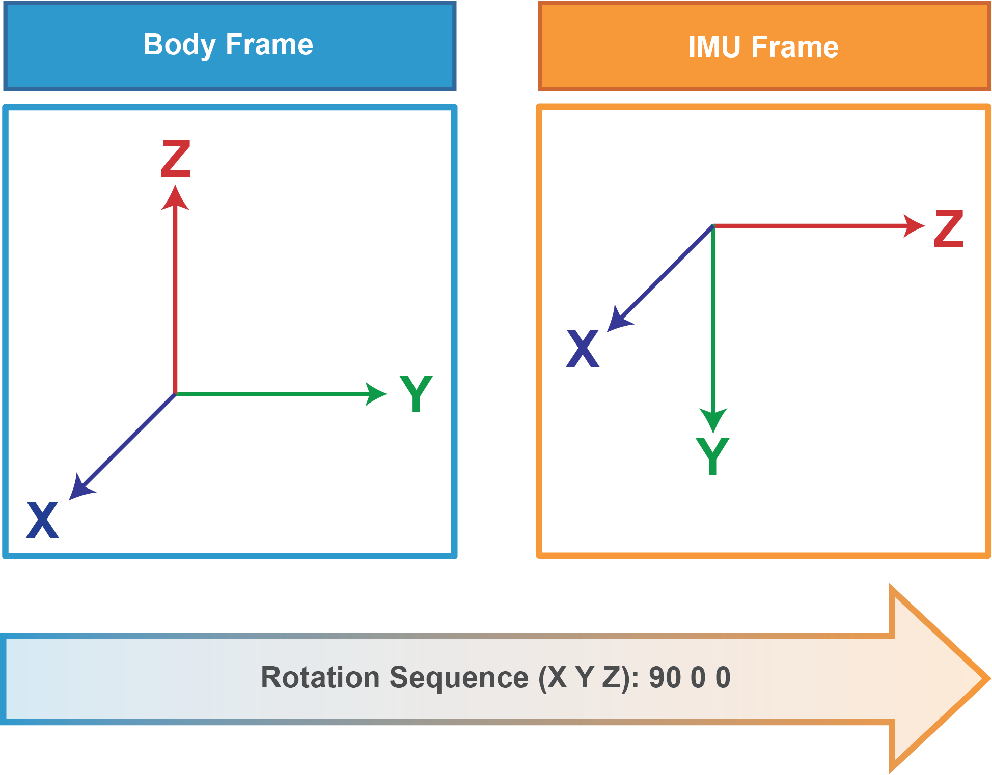
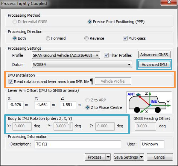
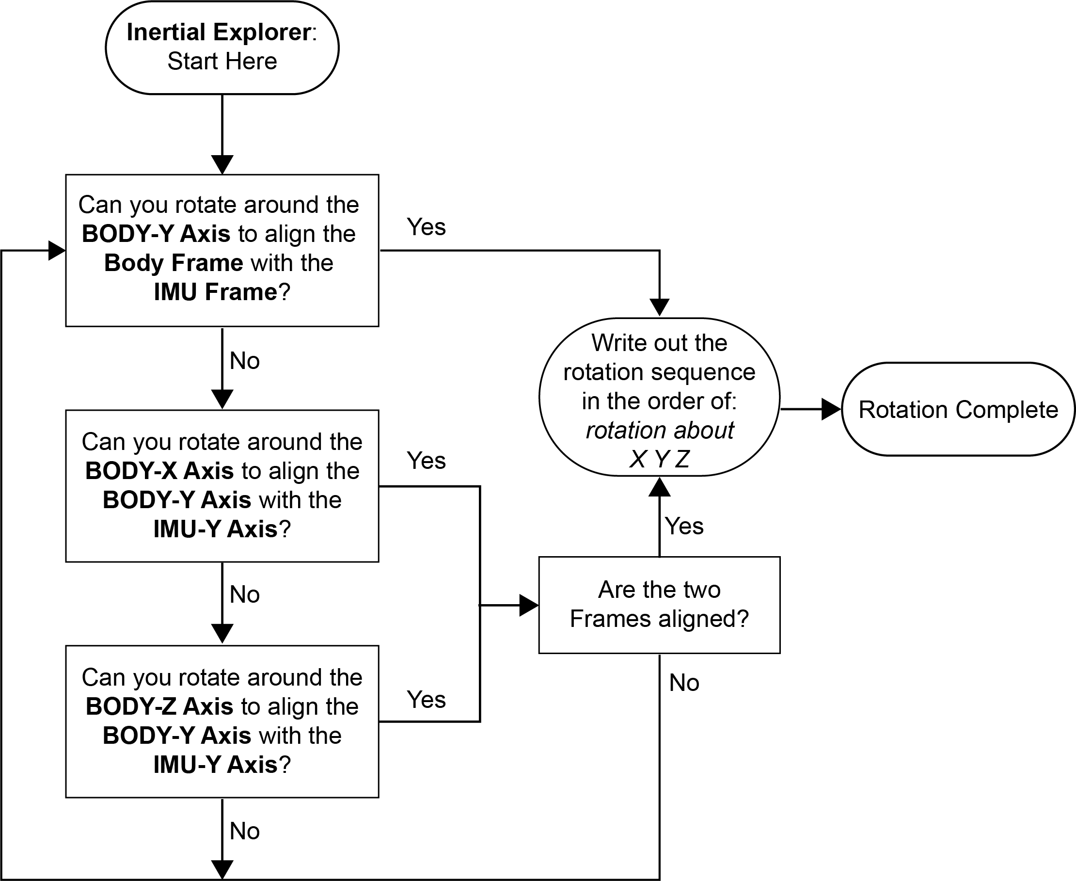
In Inertial Explorer, rotations are FROM the Vehicle Frame TO the IMU Frame, as shown in Figure: Inertial Explorer Rotations. Rotations are set in the Loosely Coupled or Tightly Coupled Processing Window pictured in Figure: Entering Rotational Offsets in Inertial ExplorerFigure 8. In this window, the Vehicle Frame is defined as the ‘Body’ Frame.
Flow Chart – Determining Rotations in Inertial Explorer
Workflow from SPAN to Inertial Explorer: Rotations
Inertial Explorer is designed to automatically read in and auto-fill set up parameters from raw SPAN data files. In order to use this built-in feature, the raw SPAN data must contain the rotation configuration. In OEM6 this is done by logging LOG VEHICLEBODYROTATION ONCHANGED; with OEM7 use LOG INSCONFIG ONCHANGED. These logs provide Inertial Explorer with information on the rotations in the SPAN setup, which are then transformed into the reference system used in Inertial Explorer, and set in the Loosely Coupled and Tightly Coupled Processing windows. As shown in Figure: Entering Rotational Offsets in Inertial Explorer, it is possible to disable this auto-fill feature in Inertial Explorer for the rotation and lever arm, in the event the values imported into the project automatically are incorrect.
For a complete list of required and recommended SPAN logs for Inertial Explorer, and more detailed information on the SPAN to Inertial Explorer workflow, please refer to the NovAtel Application Note SPAN Data Logging for Inertial Explorer.
Rotation Examples
This section is designed to provide a variety of examples that can be used to practice and become more familiar with rotations. By using the Flow Charts as a guide, the process of determining rotations should be simpler, and more intuitive. The step-by-step solutions are shown on the page following each scenario. For the purpose of this document, all examples will refer to the frames as defined in the first column of Table: Reference Frames, and as summarized below in the Quick Notes.
Quick Notes
Whether setting up a data collection or post-processing project, the following points provide a useful summary for working with rotation sequences in SPAN and Inertial Explorer:
-
SPAN OEM6: rotating FROM the Vehicle Frame TO the SPAN Computation Frame. The IMU Frame is mapped to the SPAN Computation Frame.
-
SPAN OEM7: rotating FROM the IMU Frame TO the Vehicle Frame.
-
Inertial Explorer: rotating FROM the Vehicle Frame TO the IMU Frame.
-
Rotations around the X Y Z axes are applied in the order: Z X Y.
-
Rotations around the X Y Z axes are written in the order: X Y Z.
-
The reference frames are defined in a Right Hand positive system.
-
Counter-clockwise rotations are positive.
-
By following the logging instructions in SPAN Data Logging for Inertial Explorer, configuration parameters will be automatically read and filled in to your Inertial Explorer project.
Example 1:
Example 1 – Key Points:
-
There are some cases, such as this one, where the SPAN OEM7 and Inertial Explorer rotations are the same.
-
For OEM6, the applied Mapping 6 brings the SPAN Computation Frame into alignment with the Vehicle frame, so there is no applied rotation (0 0 0).
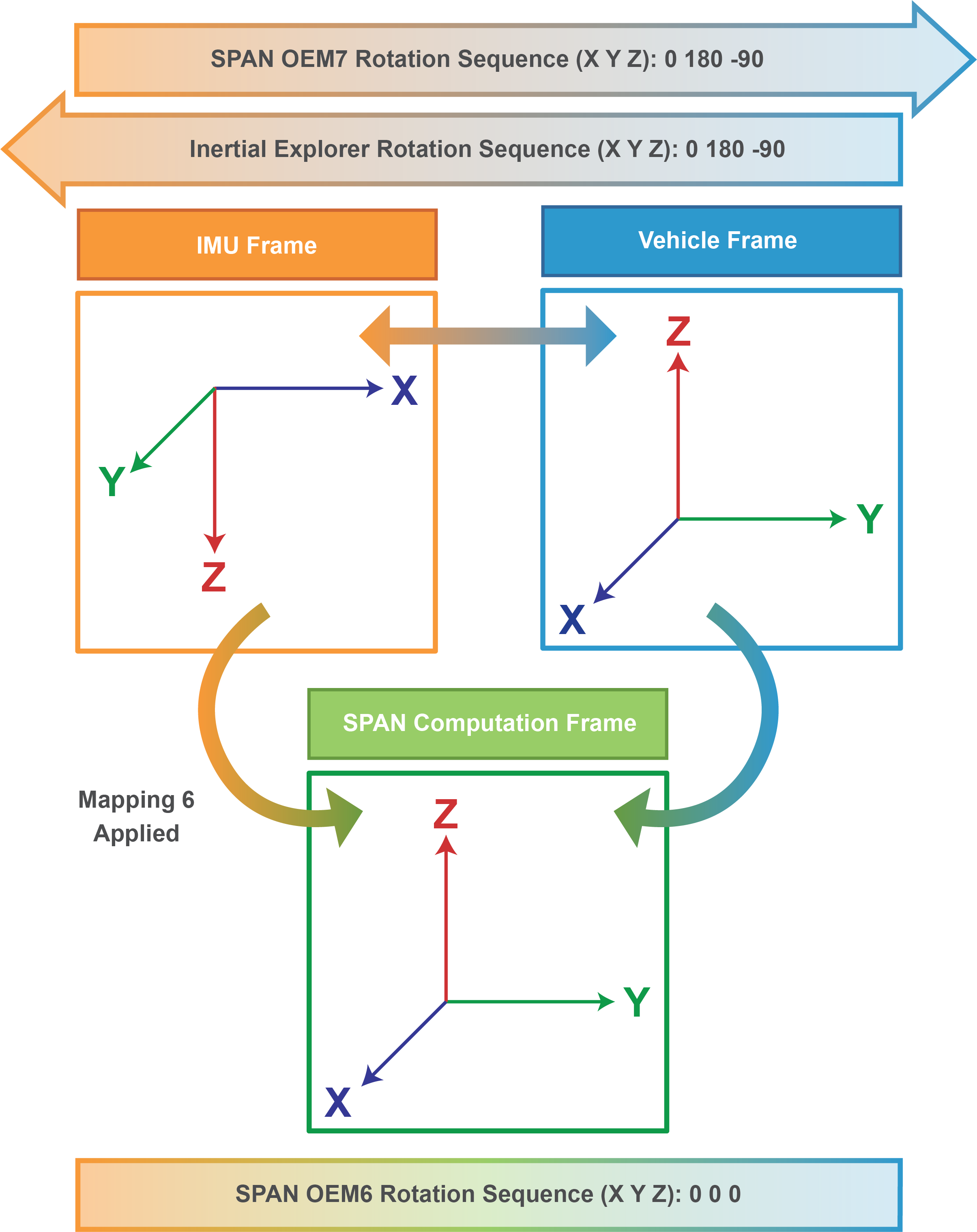
Example 1 – Rotation Sequences:
SPAN OEM7
SETINSROTATION RBV 0 180 -90

Inertial Explorer
Body to IMU Rotation: 0 180 -90

SPAN OEM6
SETIMUORIENTATION 6
VEHICLEBODYROTATION 0 0 0
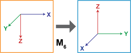
Example 2:
Example 2 – Key Points:
-
In this example, the OEM7 and Inertial Explorer rotations are not the same, highlighting the major differences that occur when the direction of the rotation is reversed.
-
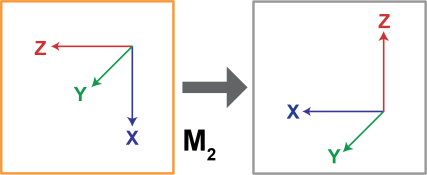
For OEM6, there is still a rotation between the SPAN Computation Frame the Vehicle Body Frame after Mapping 2 is applied.
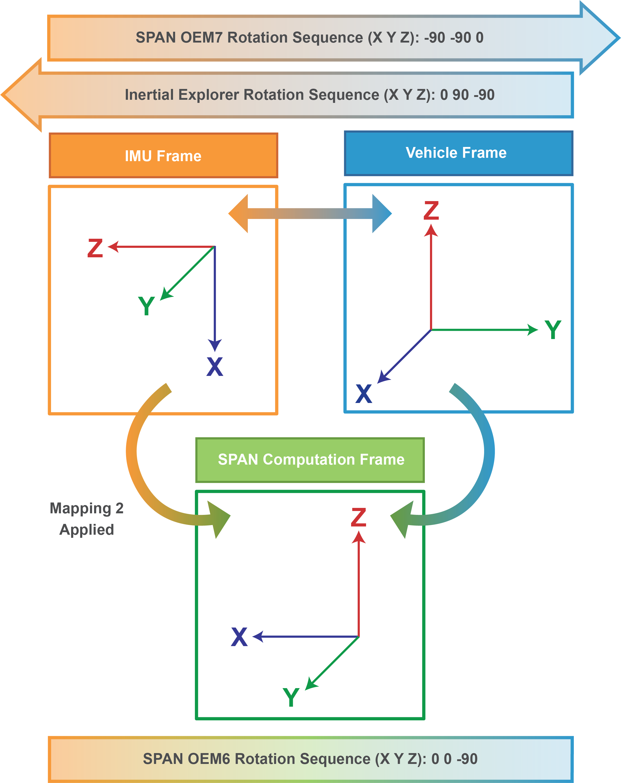
Example 2 – Rotation Sequences:
SPAN OEM7
SETINSROTATION RBV -90 -90 0

Inertial Explorer
Body to IMU Rotation: 0 90 -90

SPAN OEM6
SETIMUORIENTATION 2
VEHICLEBODYROTATION 0 0 -90
Example 3:
Example 3 – Key Points:
-
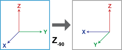
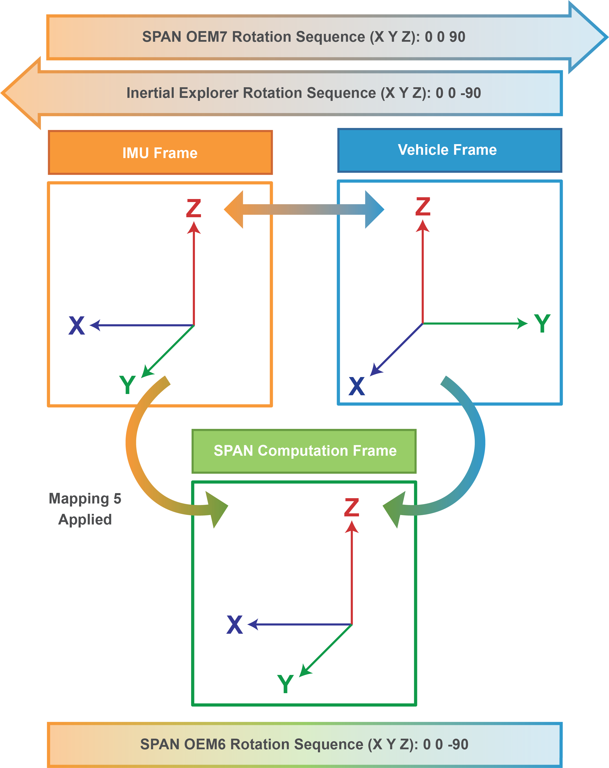
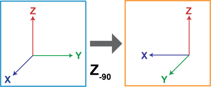
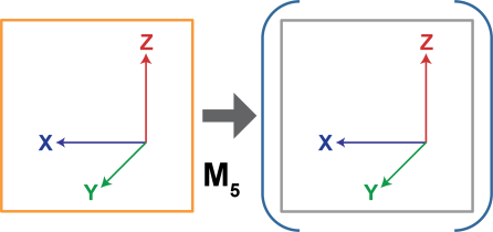
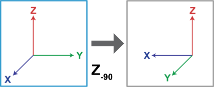
When the IMU Z axis is up, Mapping 5 is used in OEM6. As this is the default Mapping, it is not necessary to define it with the SETIMUORIENTATION command unless alignment via the SPAN kinematic alignment routine is desired. Although the SETIMUORIENTATION command is not always necessary, it is still highly recommended that it is used for later reference and post-processing.
-
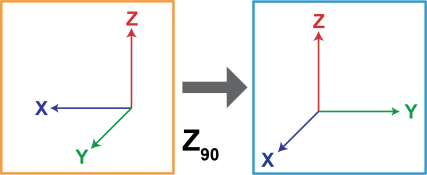
In this example, the OEM6 and OEM7 rotations are the same. This is because the IMU Frame is in the Default Mapping 5 position, which means the SPAN Computation Frame is equivalent to the IMU Frame.
Example 3 – Rotation Sequences:
SPAN OEM7
SETINSROTATION RBV 0 0 90
Inertial Explorer
Body to IMU Rotation: 0 0 -90
SPAN OEM6
SETIMUORIENTATION 5 (Optional)
VEHICLEBODYROTATION 0 0 -90
Additional Information
OEM User Manuals
Further details on the logs and commands outlined in this document can be found in the NovAtel OEM User Manuals.
OEM6:
SPAN on OEM6 Firmware Reference Manual:
OEM6 Family Firmware Reference Manual:
OEM7:
OEM7 Family Firmware Reference Manual:
https://docs.novatel.com/OEM7/Content/PDFs/OEM7_Commands_Logs_Manual.pdf
Documentation Portal:
Waypoint Product Manuals:
Detailed instructions on using Inertial Explorer 8.80 can be found in the Waypoint User Manual: https://docs.novatel.com/Waypoint/Content/PDFs/Waypoint_Software_User_Manual_OM-20000166.pdf
Or they can be found through the Waypoint documentation portal:
https://docs.novatel.com/Waypoint/Content/Home.htm
Support:
To search for more information or submit a support case, please visit NovAtel’s support page: https://www.novatel.com/support/
APN-065: Determining Rotations in SPAN & Inertial Explorer
