Install a MIC in a Stack Up Configuration
In a stack up configuration, the MIC is connected to an OEM719 receiver using the 20-pin header on the OEM719. Power and communications connections to the receiver are made through the MIC.
Important! Assemble in accordance with applicable industry standards. Ensure all Electrostatic Discharge (ESD) measures are in place, in particular, use a ground strap before exposing or handling any electronic items, including the MIC, receiver and IMU. Take care to prevent damaging or marring painted surfaces, O-rings, sealing surfaces and the IMU.
For more information about ESD practices, see Electrostatic Discharge (ESD) Practices.
Basic Set Up – MIC in Stack Up Configuration
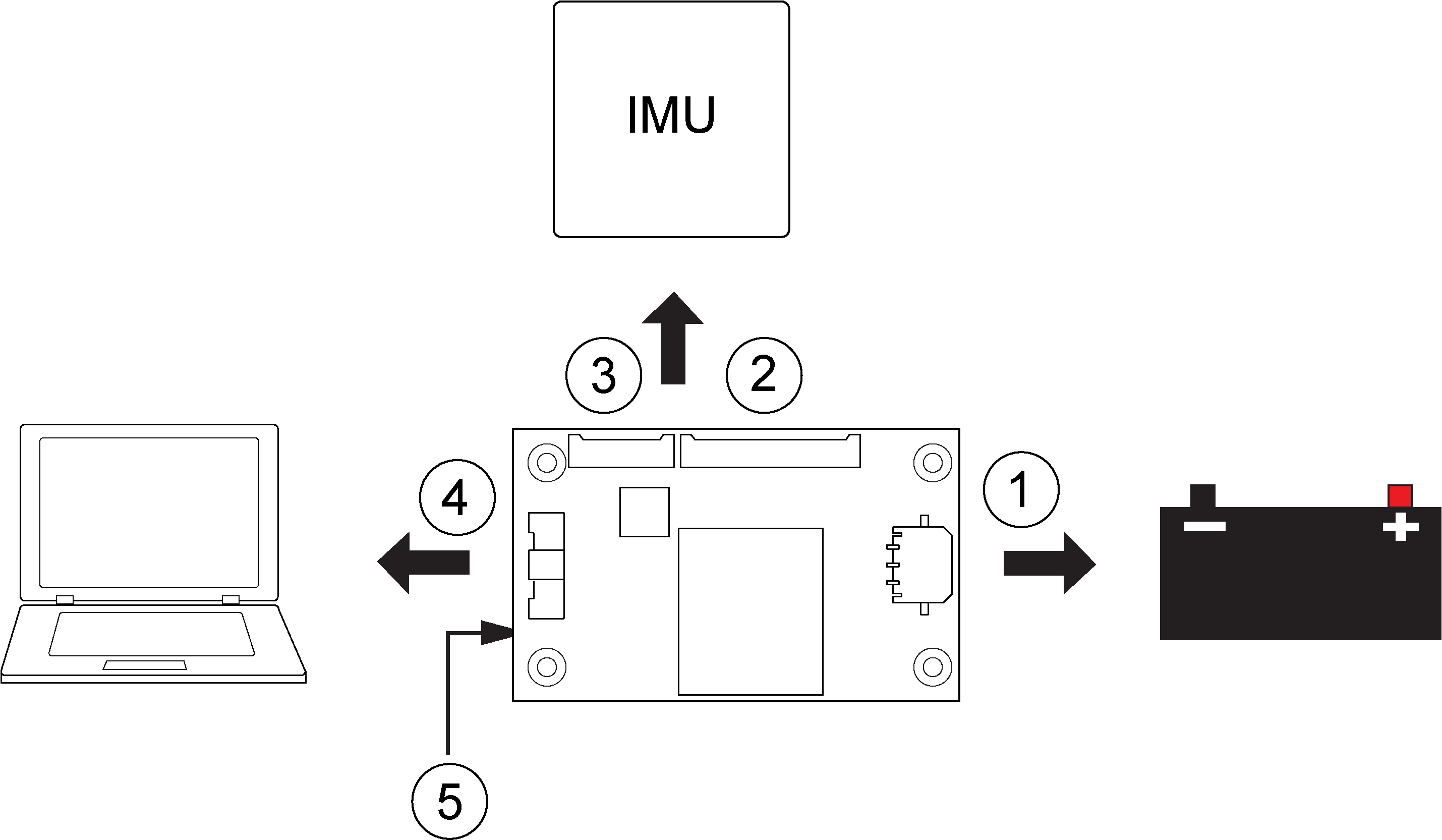
|
Ref |
Connector |
Part Number |
Mating Connector |
Description |
|---|---|---|---|---|
|
1 |
P101 |
43650-0313 |
43645-0300 |
Connects to the MIC power supply. |
|
2 |
P601 |
53780-2070 |
51146-2000 |
Connects to HG1700, OEM-HG1900, OEM-HG1930 and OEM-IMU-STIM300 IMUs. (NovAtel supplied cable kit) |
|
3 |
P701 |
53780-1070 |
51146-1000 |
Connects to OEM-IMU-ADIS-16488 IMUs. |
|
4 |
P301 |
501571-3007 |
501189-3010 |
Connects the MIC and OEM719 communication signals to the user system. (user supplied cable) |
|
5 |
J301 |
ASP-163577-01 |
N/A |
Connects to the main connector (P1701) on an OEM719 receiver. J301 is on the bottom of the MIC card |
For information about the MIC connectors and pin-outs, see MIC Connectors.
For information about the OEM7 receiver card connectors and pinouts, refer to Technical Specifications.
Use the following steps to install the OEM719 receiver and MIC:
-
Mount the components of the SPAN system. See Mount the SPAN System Components.
-
Connect the IMU to the MIC. See Connect the IMU to the MIC.
-
Connect power to the MIC. See Connect Power to the MIC.
-
Connect the input and output signals to the MIC. See Connect the Input and Output Signals.