Mount the SPAN system components
-
Mount the antenna.
-
Use the standoffs supplied with the MIC card to secure the OEM719 to its mounting location.
See Figure: Mount the MIC on the OEM719.
See
The part number for the recommended standoffs is RAF-M21073005AL7 (Irwin Industrial).
If alternate standoffs are selected, use equivalent parts with a minimum height of 12 mm.
Ensure all standoffs are properly installed and the mounting location is flat.
The amount of board deflection (bow and twist) must not exceed 0.75%. For example, on the MIC which is 75 mm long and 46 mm wide, the deflection along the length must not exceed 0.56 mm and the deflection along the width must not exceed 0.34 mm.Ensure the MIC is mounted close enough to the IMU so the interface cable can reach both devices.
-
Connect the antenna cable to the antenna jack on the OEM719.
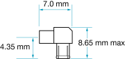
The antenna cable must have a right angle MCX connector on the end that connects to the OEM719.
Warning! Do not apply power to the cards until the antenna cable is attached.
The part number for the recommended MCX connector is M1051-110 (ShinA Telecom). If an alternate part is used, it should meet the dimensions shown in the diagram.
The space between the OEM719 and the MIC is limited. The height of the MCX connector must not exceed 8.65 mm.
-
Align the mating connector (J301) on the MIC with the 20-pin header (P1701) on the OEM719.
Make sure all of the pins on the header are aligned with the holes in the mating connector.
Press down on the MIC to seat the connector on the header.
-
Use the four screws supplied with MIC to secure the MIC card to the OEM719.
