CPT7 Installation Overview
A CPT7 system consists of a CPT7, a GNSS antenna, power and a communication link (if your application requires real time differential operation). The following diagrams show typical CPT7 installations.
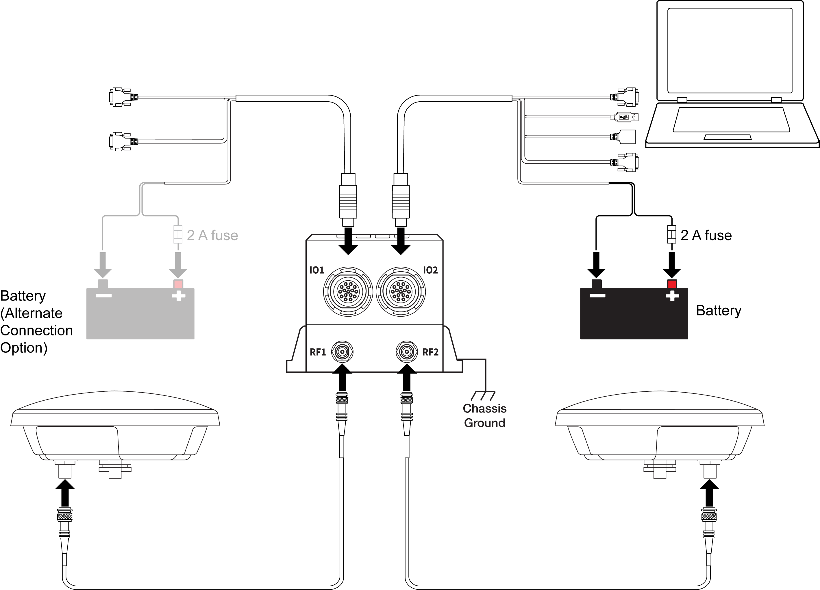
Typical Installation of a CPT7 System
Typical Installation of a CPT7700 System
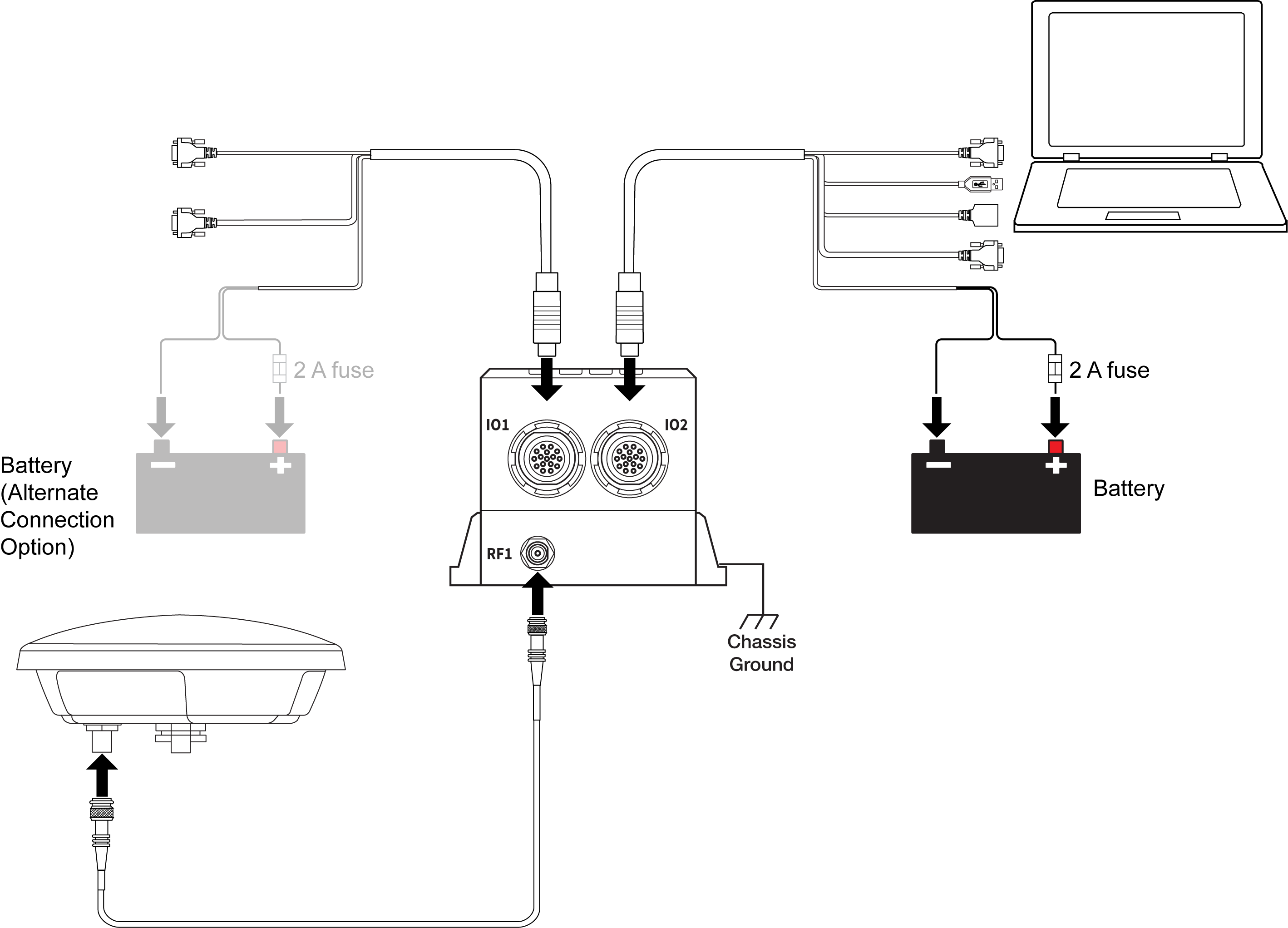
Power can be connected to either the IO1 or IO2 port.
Do not connect a power supply to both ports.
Complete the following steps to set up your CPT7 system.
-
Mount the GNSS antenna.
See Mounting the GNSS Antenna for details.
-
Mount the CPT7.
See Mount the CPT7 for details.
-
Connect the primary GNSS antenna to the RF1 port.
Connect the secondary GNSS antenna to the RF2 port (CPT7 only).Use an SMA torque wrench to tighten the connection to 0.9 Nꞏm (8 in-lbs) maximum.
The CPT7 supplies +5 VDC (200 mA maximum) to the antenna LNA through the center conductor of the antenna cable. See Antenna LNA Power for more information.
-
Connect the Event input and output signals (optional).
See Connect I/O Signals to the CPT7 for details.
-
Connect power to the CPT7.
See Connect Power to the CPT7 for details.
-
Connect a data communication device, such as a computer, to the CPT7. A data communication device is used to configure and monitor the receiver.
See Connect the CPT7 to Data Communication Equipment for details.
Prior to installation of a CPT7 system, please review the following sections:
Importance Of Lever Arms
Importance of RBV Calibration
Importance of Antenna Location for ALIGN
Vibration Considerations
Following these guidelines will help deliver the best performance from the system.