SPAN translations and rotations – SMART7
|
Platform: |
SMART7-S, SMART7-SI |
A SPAN system combines GNSS and INS into a single system. In a GNSS system, the position is reported relative to the phase centre of the GNSS antenna. In an INS system, the position, velocity and attitude data is reported relative to the centre of navigation of the IMU. For a SPAN system to provide a combined GNSS+INS position, velocity and attitude, it must know where the GNSS antenna is positioned relative to the IMU.
The orientation of the IMU relative to the forward direction of the vehicle is also needed to convert the velocity and attitude changes sensed by the IMU into the actual motion of the vehicle.
If the SPAN system incorporates other devices, the SPAN system also needs to know the location and orientation of these additional devices relative to the IMU.
Translational offsets
The three dimensional distances between the IMU and other SPAN components are called translational offsets.
The translational offsets are measured in three directions, X axis, Y axis and Z axis, typically relative to the IMU Body frame. Translational offsets can also be entered relative to the Vehicle frame.
The X, Y and Z axes of the IMU Body frame are indicated on the SMART7 mechanical drawings. See SMART7 mechanical specifications.
The translational offsets from the IMU to the GNSS antenna are required for all SPAN systems. Since the IMU and GNSS antenna are inside the SMART7 enclosure, the IMU to antenna offset is configured at the factory. No additional translational offset configuration is needed on the SMART7, unless there are additional SPAN system components that require an offset.
Do not use the SETINSTRANSLATION ANT1 command to change the IMU to primary antenna offset. Changing this value from the factory default will impair SPAN system performance.
Some SPAN systems may have other sensors or devices integrated into the system for which the SPAN needs translational offsets. For example, a second receiver and GNSS antenna in a SPAN ALIGN system. The offsets to these additional sensors and devices are also entered using the SETINSTRANSLATION command.
Figure: ALIGN translation offset shows an example of the translational offsets between a SMART7-S and a SMART7 in an ALIGN configuration. In this example, the SMART7-S is mounted at rear left corner of the tractor roof and the IMU Body Frame of the SMART7-S (indicated by the small arrows) has the X axis pointing in the direction of the vehicle motion and the z axis pointing down.
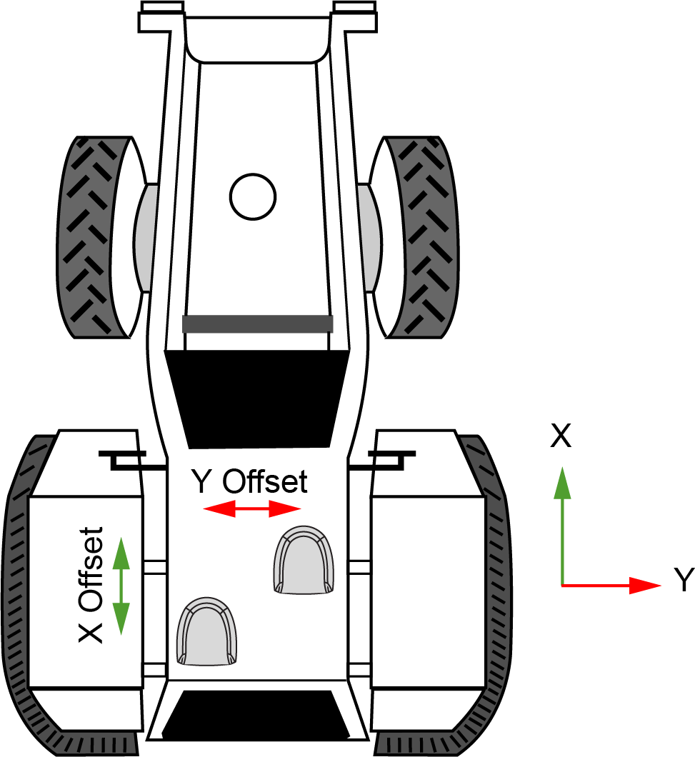
If the distances measured in this example were X Offset = 1.5 m, Y Offset = 1 m and Z Offset = 0 m, the following values would be entered, based on the IMU Body Frame:
-
x = 1.5
-
y = 1.0
-
z = 0
The translational offsets are entered using the SETINSTRANSLATION command. For this example, the command to enter these offsets is:
SETINSTRANSLATION ANT2 1.5 1.0 0
The measurements for the translational offsets should be done as accurately as possible, preferably to within millimetres especially for RTK operation. Any error in the offsets will translate into an error in the INS position.
By default, the translational offsets are entered in the IMU Body frame. However, in some systems the IMU Body frame may not be known precisely. For these cases, the SETINSTRANSLATION command has an option that allows the offsets to be entered relative to the Vehicle frame. In these cases, the rotation from the IMU Body frame to the Vehicle frame (RBV) is used to rotate offsets into the default IMU Body frame as required. To achieve the best results, this means that the RBV rotation must be known very precisely. Typically this is achieved through the SPAN RBV Calibration procedure. See Body to vehicle frame rotation calibration routine or Multi-line body to vehicle frame rotation calibration routine for information about this calibration procedure.
Rotational offsets
The differences in orientation between the SMART7 and other SPAN components are called rotational offsets. Rotational offsets are given as the rotation from the IMU Body frame to the frame of interest.
The order of rotations is Z-X-Y and all rotations are right handed.
Generally, frames of reference are defined as Z up, with Y forward, and X completing the right-handed system. An example is the Vehicle frame, where Z is always considered to be upwards, Y forward through the direction of travel, and X to the right.
If the SMART7 is installed with the front of the SMART7 facing the direction of forward motion for the vehicle (as shown in Figure: SMART7 orientation), an IMU Body frame to Vehicle frame rotation is not required. The necessary rotations are configured at the factory.
An IMU Body frame to Vehicle frame calibration routine should be run to on all SMART7 installations, whether an IMU Body frame to Vehicle frame rotation is required or not. See Body to vehicle frame rotation calibration routine or Multi-line body to vehicle frame rotation calibration routine for more information. This calibration routine should be done each time the SMART7 is remounted.
Non-standard installation
The SMART7 is intended to be installed with the front of the SMART7 facing the direction of vehicle travel. If the installation location does not allow this orientation, the SETINSROTATION RBV command must be used to align the SMART7 IMU Body frame with the Vehicle frame.
The IMU Body frame of the SMART7-S is shown in Figure: SMART7-S and SMART7-SI IMU body frame.
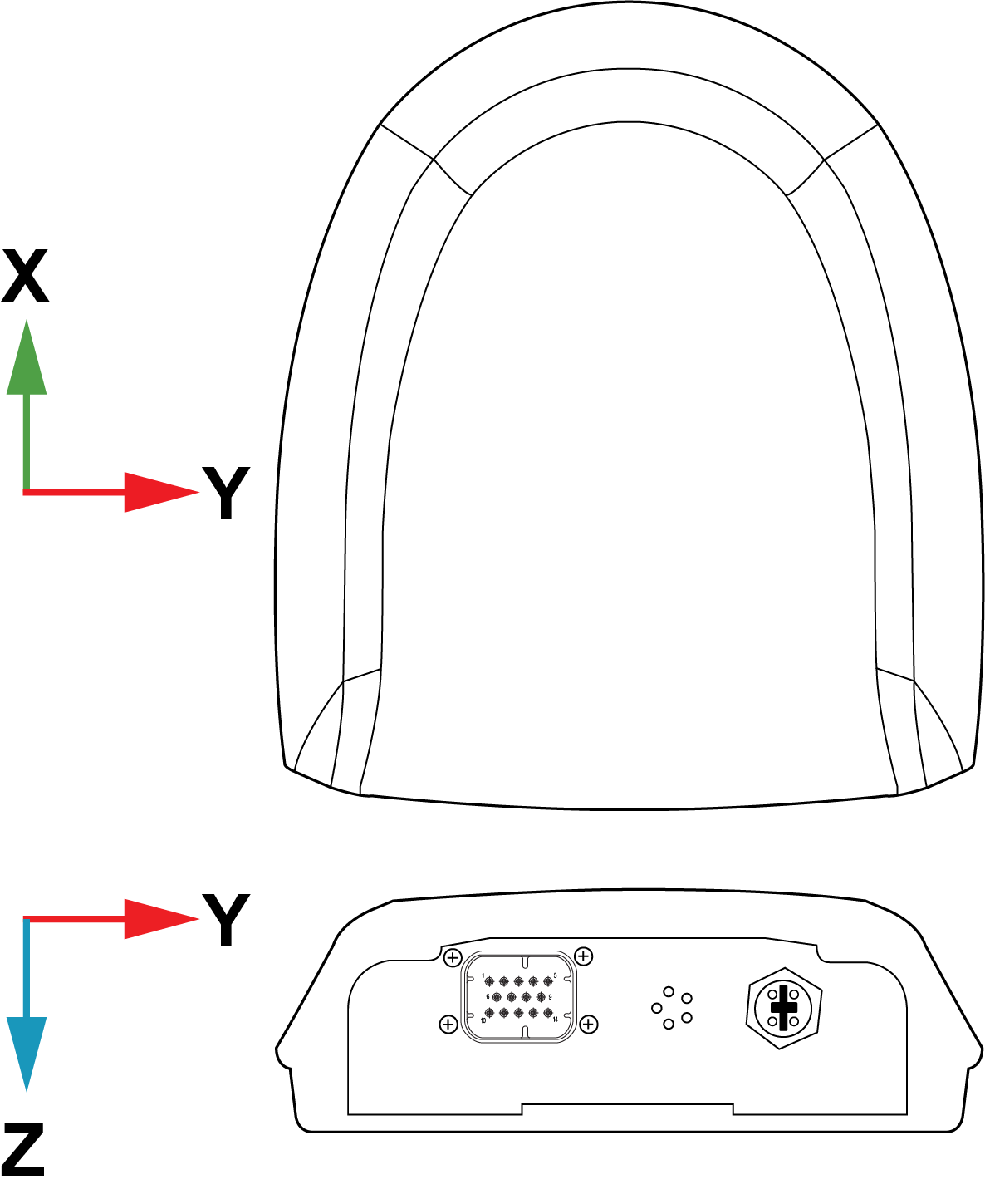
At the factory, the following command is entered to configure rotations required to align the IMU Body frame so that the Z axis points up and the Y axis points out the front of the SMART7-S. See Figure: SMART7-S and SMART7-SI IMU body frame with factory configured rotation.
SETINSROTATION RBV 180 0 90

If SMART7-S is not installed with the front of the SMART7-S facing the direction of vehicle travel, a different set of rotations must be entered using the SETINSROTATION RBV command.
Rotational offsets – example
Consider a SMART7-S installed as shown in the following diagram. In this installation, the factory configured rotation does not align the IMU Body frame with the Vehicle frame. Therefore, a new IMU Body to Vehicle frame rotation must be entered using the SETINSROTATION RBV command.
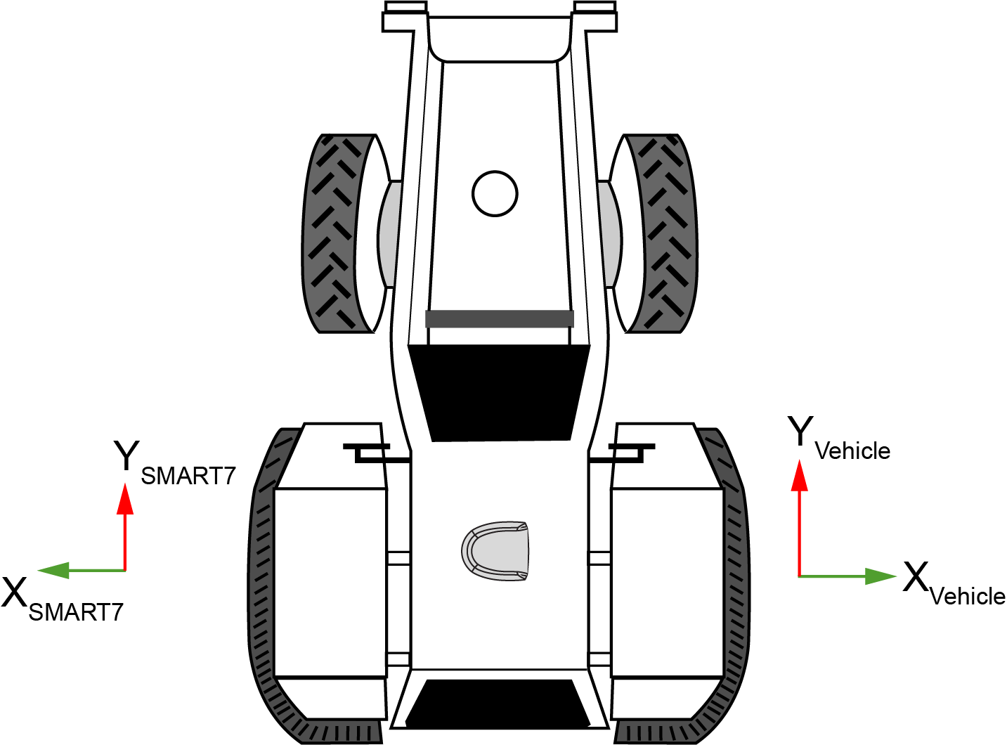
In this example, the Euler Angles to rotate from the IMU Body frame (Figure: SMART7-S and SMART7-SI IMU body frame) to the Vehicle frame (RBV) are:
-
X: 0
-
Y: 180
-
Z: 0
To reach this answer, keep in mind the following rules:
-
You must rotate from the IMU Body frame to the Vehicle frame.
-
You must rotate in the order Z, X, Y. Specifically Z, X', Y"
-
Positive rotation is defined according to the right hand rule.
The following diagram shows the IMU Body frame of the SMART7-S and the Vehicle frame for the example installation shown in Figure: SMART7-S installed with orientation not aligned with vehicle frame.
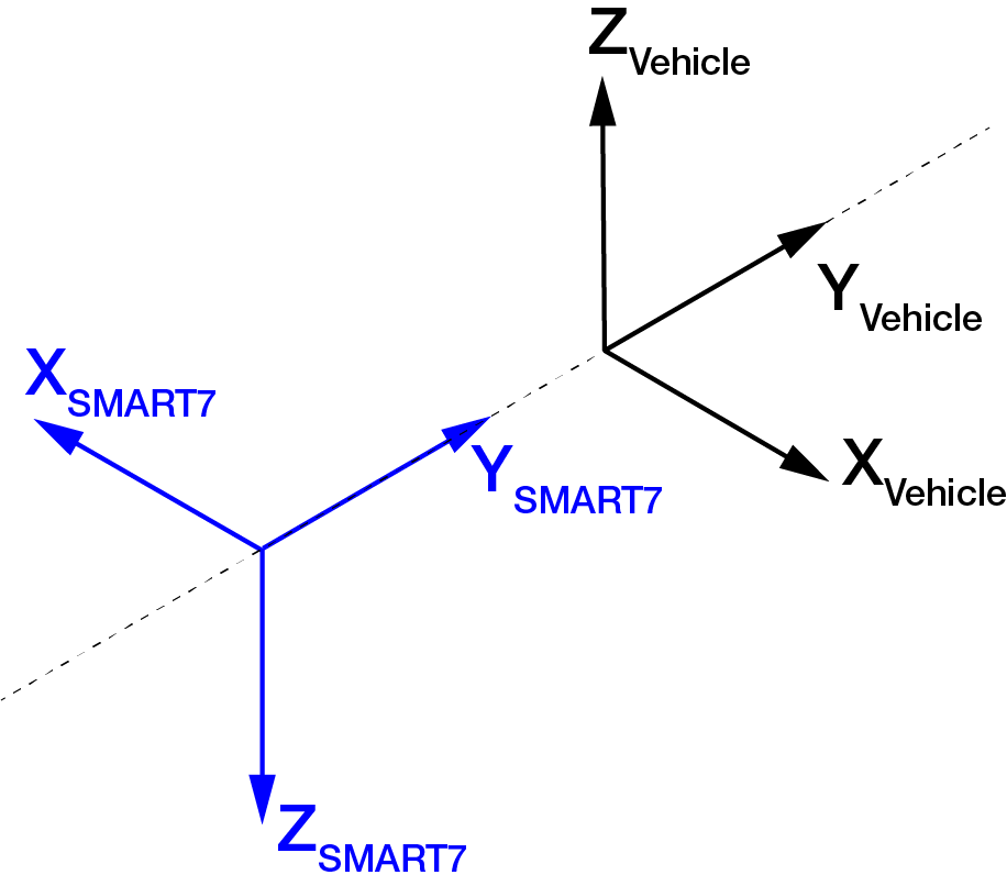
Z Rotation:
Since the Y axis of the IMU Body frame is collinear with vehicle Y axis, a Z rotation is not required.
X Rotation:
Since the Y axis of the IMU Body frame is collinear with the vehicle Y axis, an X rotation is also not required
Y Rotation:
Observe that if a 180 degree rotation is performed about the IMU Body frame Y axis, the rotated IMU Z axis is now collinear with the Vehicle Z axis, and the rotated IMU X axis is also collinear with the Vehicle X axis.
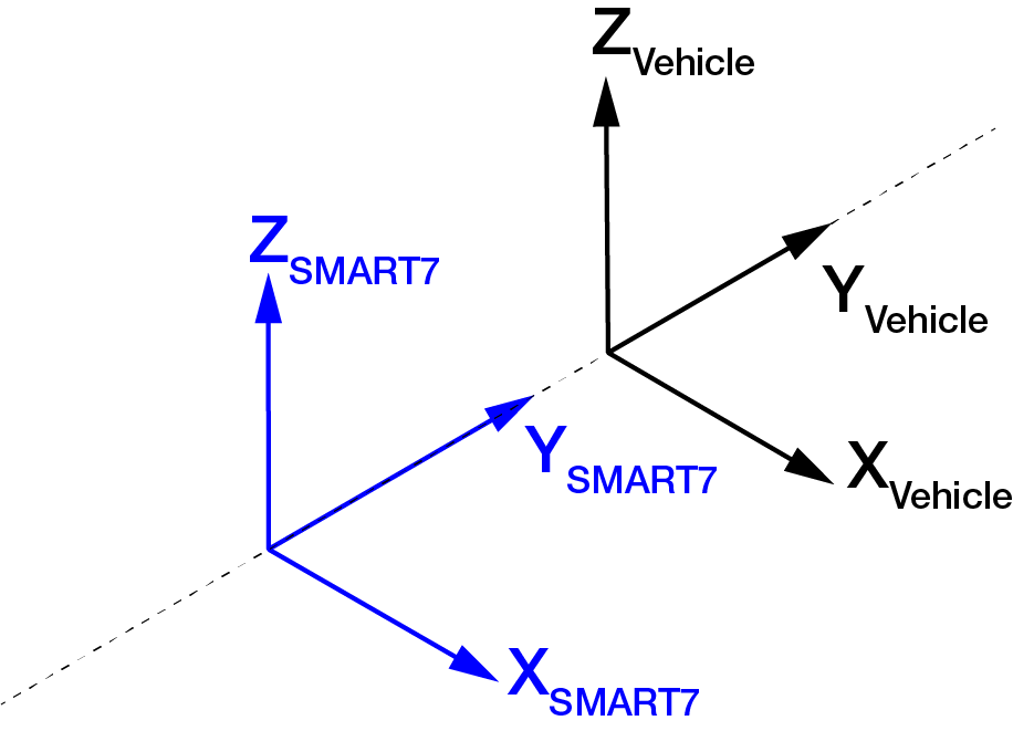
This solution is not unique. Due to the properties of Euler Angles, there are usually multiple sets of equivalent rotations.
The rotational offsets are entered using the SETINSROTATION command. For this example, the command to enter the rotations for the previous example is:
SETINSROTATION RBV 0 180 0