Transferring time between receivers
|
Platform: |
OEM719, OEM729, OEM7500, OEM7600, OEM7700, OEM7720, PwrPak7, CPT7, CPT7700 |
The ADJUST1PPS command is used as part of the procedure to transfer time between receivers. The number of Pulses Per Second (PPS) is always set to 1 with this command. It is typically used when the receiver is not adjusting its own clock and is using an external reference frequency.
The TIMESYNC log is also used to synchronize time between receivers. It contains a time status field that may show COARSE or FINE, among others. For a complete list of the time status values and definitions, refer to GPS reference time status.
Procedures to transfer time provides details on the time transfer procedure. Terms used in the procedure are defined in Time definitions. Refer also to the ADJUST1PPS command and the TIMESYNC log.
GPS to receiver time synchronization
Receiver time synchronization with GPS time does not occur until the receiver locks onto the first satellite. The GPS L1 signal has two main streams of data modulated on the carrier. These data streams are the C/A code (1.023 MHz rate) and the P(Y) code (10.23 MHz rate). Additionally, a navigation message (at a 50 Hz rate) contains GPS satellite data including the ephemeris, clock corrections and constellation status. This navigation message is encoded on both the C/A and P(Y) codes. The navigation message is transmitted via individual subframes and each subframe is 300 bits in length. With the 50 Hz data bit rate there is a new subframe transmitted every six seconds.
Time definitions
The following are related definitions:
Coarse Time
Each subframe contains the transmit time of the next subframe in seconds of GPS Time of Week (TOW). After the first subframe is collected and decoded by the receiver, an approximate calculation of the receiver clock offset can be made. The receiver clock offset is the difference between GPS time and internal receiver time. The calculation is based on subframe transmit time and the approximate propagation time from the satellite signal to the receiver. The position of the satellite and receiver clock offset are used to re-initialize the seconds counter on the receiver, resulting in receiver/GPS time synchronization. The accuracy of the receiver time is expected to be within 30 milliseconds (ms) of GPS time. This initial synchronization is referred to as coarse time and is indicated by COARSE in the time status field of the TIMESYNC log.
Fine Time
When at least four satellites are acquired to calculate the antenna position, a more accurate estimate of the receiver clock offset is calculated. The new receiver clock offset is used to synchronize the receiver clock even closer to GPS time. This is referred to as fine time and appears as FINE or FINESTEERING in the time status field of the TIMESYNC log. Fine time accuracy is a function of the GPS constellation status and is influenced by external receiver RF delay. For the Standard Position Service (SPS) the time accuracy is specified as 20 ns (1 sigma) with internal compensation.
Fine Clock
An OEM7 receiver that is tracking satellites and has a FINE or FINESTEERING receiver clock state.
Cold Clock
An OEM7 receiver that needs to have its clock synchronized with the Fine receiver. It may have any clock state (except FINE or FINESTEERING) that includes UNKNOWN.
Warm Clock
An OEM7 receiver that has its clock adjusted to greater than 500 ms. Refer to the TIME log to view the clock offset.
Procedures to transfer time
These procedures are used to transfer time between a fine clock and a cold or warm clock GPS receiver.
|
|
When connecting two receivers to transfer time, disable responses on the COM port used to connect the receivers by issuing the following command on both receivers: interfacemode comX novatel novatel off Where comX is the port used on the receiver. |
Transfer COARSE time (<10 ms) from a Fine clock to a Cold clock GPS receiver
-
Connect a COM, USB or Ethernet port from the fine clock receiver to the cold clock receiver (for example, COM2 on the fine clock receiver to COM3 on the cold clock receiver) as shown in Figure: Transfer COARSE time from Fine clock to Cold clock receiver. Configure both ports to the same baud rate and handshaking configurations.
-
Issue the following command to the fine clock receiver:
log com2 timesyncb ontime 1
-
Issue the following command to the cold clock receiver:
adjust1pps time
When the cold clock receiver receives the TIMESYNC log, it sets its clock with a 100 ms transfer delay allowance.
Transfer FINE time (<50 ns) from a Fine clock to a Cold clock GPS receiver
-
Connect a COM, USB or Ethernet port from the fine clock receiver to the cold clock receiver (for example, COM2 on the fine clock receiver to COM3 on the cold clock receiver), as shown in Figure: Transfer FINE time from Fine clock to Cold clock receiver. Configure both ports to the same baud rate and handshaking configurations.
-
EVENTINCONTROL MARK1 ENABLE
-
Issue the following command to the fine clock receiver:
log com2 timesyncb ontime 1
-
Connect the 1PPS signal of the fine clock receiver to the Mark 1 input (Event1) of the cold clock receiver.
-
Issue the following command to the cold clock receiver:
adjust1pps markwithtime
When the cold clock receiver receives the 1PPS event from the fine clock receiver, it checks to see if a valid TIMESYNC log has arrived within 200 ms of the last 1PPS event. If so, it sets the cold clock receiver clock to the time of the fine clock receiver. See Figure: 1 PPS alignment.
Transfer FINE time from a Fine clock to a Warm clock GPS receiver
-
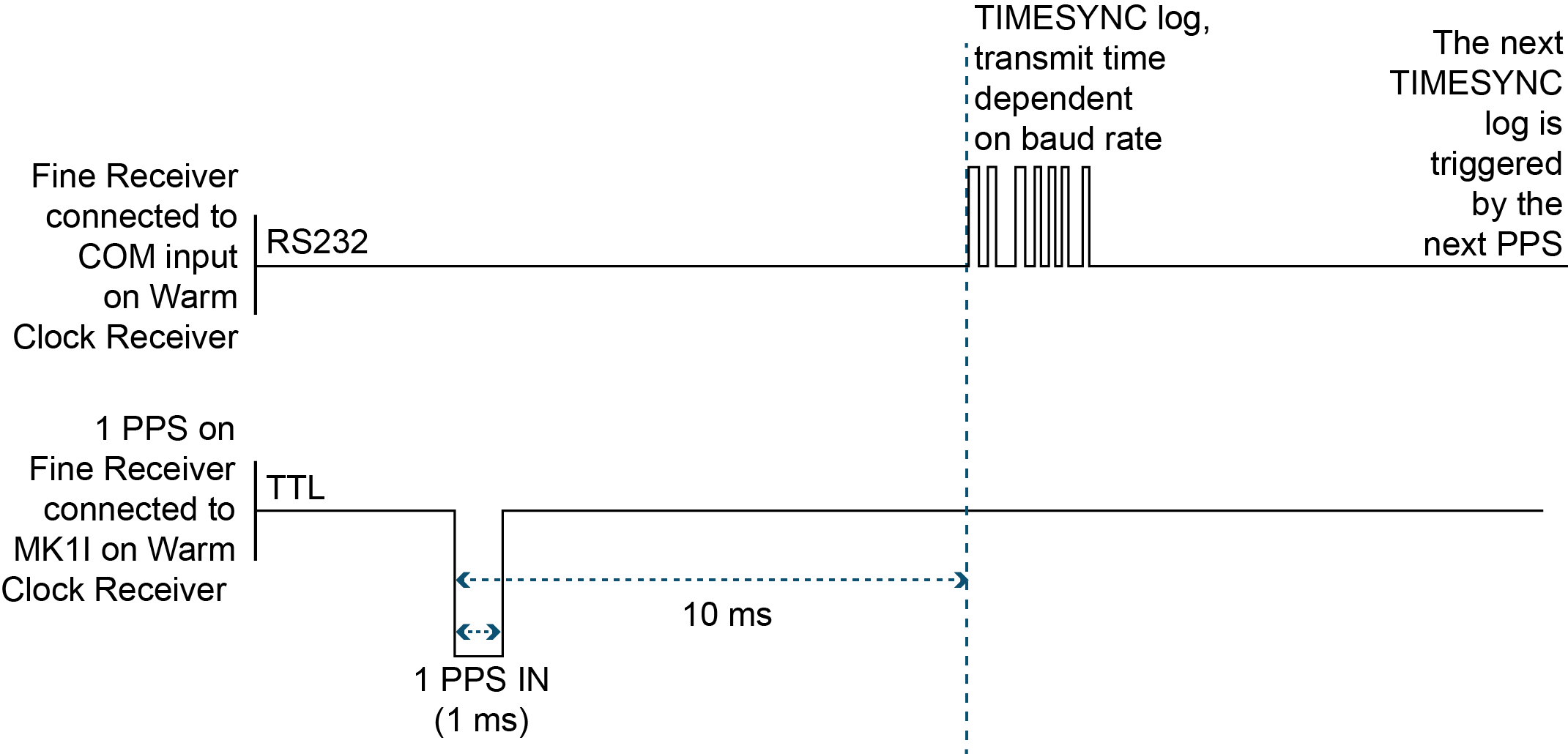
Connect the 1 PPS signal of the fine clock receiver to the Mark 1 input (Event1) of the warm clock receiver as shown in Figure: Transfer FINE time from Fine clock to Warm clock receiver.
-
EVENTINCONTROL MARK1 ENABLE
-
Issue the following command to the warm clock receiver:
adjust1pps mark
The phase of the warm clock receiver clock is adjusted by the fractional measurement of the fine clock receiver’s 1 PPS mark input event. In other words, it synchronizes the warm clock receiver’s 1 PPS to the incoming 1 PPS of the fine clock receiver. It does not adjust the one second TOW counter or the receiver’s week number. This procedure is used to make small corrections to the warm clock receiver’s clock.
If Receiver 2 is not in coarsetime, the input is ignored.
The examples shown in Figure: Transfer COARSE time from Fine clock to Cold clock receiver, Figure: Transfer FINE time from Fine clock to Cold clock receiver and Figure: Transfer FINE time from Fine clock to Warm clock receiver are for the transfer of time. If a position is needed, the receiver must be tracking satellites and must have a valid almanac.