ADJUST1PPS
Adjusts the receiver clock
|
Platform: |
OEM719, OEM729, OEM7500, OEM7600, OEM7700, OEM7720, PwrPak7, CPT7, CPT7700, SMART7, SMART2 |
Use this command to adjust the receiver clock or as part of the procedure to transfer time between receivers. The number of pulses per second (PPS) is always set to 1 Hz with this command. It is typically used when the receiver is not adjusting its own clock and is using an external reference frequency.
To disable the automatic clock adjustment, refer to the CLOCKADJUST command. To configure the receiver to use an external reference oscillator, see the EXTERNALCLOCK command.
The ADJUST1PPS command can be used to:
-
Manually shift the phase of the clock
-
Adjust the phase of the clock so the output 1PPS signal matches an external signal
-
Set the receiver clock close to that of another GNSS receiver
-
Set the receiver clock exactly in phase of another GNSS receiver
|
|
|
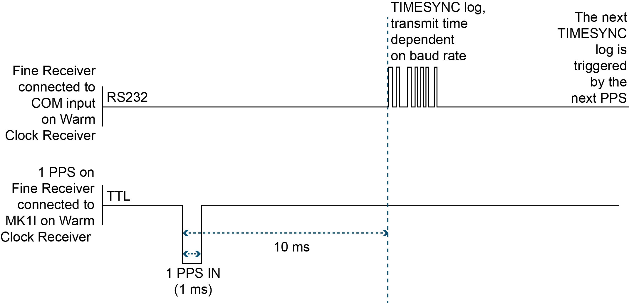
Figure: 1PPS alignment shows the 1PPS alignment between a Fine and a Warm Clock receiver. See also the TIMESYNC log and Transferring time between receivers.
The 1PPS is obtained from different receivers in different ways.
In Figure: 1PPS alignment, the examples are for the transfer of time. If you need position, you must be tracking satellites and your receiver must have a valid almanac.
Alternatively, the 1PPS signal can be set up to be output on a COM port using the COMCONTROL command. The accuracy of the 1PPS is less using this method, but may be more convenient in some circumstances.
|
OEM719 |
OEM729 |
OEM7600 |
OEM7700 |
OEM7720 |
PwrPak7 |
CPT7 |
|---|---|---|---|---|---|---|
|
COM1 Tx |
COM1 Tx |
COM1 Tx |
COM1 Tx |
COM1 Tx |
COM1 Tx |
COM1 Tx |
|
COM2 Tx |
COM2 Tx |
COM2 Tx |
COM2 Tx |
COM2 Tx |
COM2 Tx |
COM2 Tx |
|
|
COM2 RTS |
COM2 RTS |
COM2 RTS |
COM2 RTS |
|
|
|
|
COM3 Tx |
COM3 Tx |
COM3 Tx |
COM3 Tx |
COM3 Tx |
|
|
|
|
COM4 Tx |
COM4 Tx |
COM4 Tx |
|
|
|
|
|
COM5 Tx |
COM5 Tx |
COM5 Tx |
|
|
To find out the time of the last 1PPS output signal, use the TIMESYNCA/B output message (see the TIMESYNC log) which can be output serially on any available COM port, for example:
LOG COM1 TIMESYNCA ONTIME 1
Message ID: 429
Abbreviated ASCII syntax:
ADJUST1PPS mode [period] [offset]
Factory default:
ADJUST1PPS OFF
ASCII example:
ADJUST1PPS MARK CONTINUOUS 250
|
|
Use the ADJUST1PPS command to synchronize two OEM7 cards in a primary/secondary relationship to a common external clock. At the Primary Receiver: LOG COM2 TIMESYNCA ONTIME 1 INTERFACEMODE COM2 NOVATEL NOVATEL OFF CLOCKADJUST DISABLE EXTERNALCLOCK OCXO 10MHZ (choose rubidium, cesium or user instead and choose 5MHz instead if necessary) At the Secondary Receiver: INTERFACEMODE COM2 NOVATEL NOVATEL OFF CLOCKADJUST DISABLE ADJUST1PPS MARK (or markwithtime or time depending on your connection (see Figure: ADJUST1PPS connections) EXTERNALCLOCK OCXO 10MHZ (you can choose rubidium, cesium or user instead and choose 5MHz instead if necessary) Connections: Null modem cable connected from Primary COM2 to Secondary COM2 OCXO signal sent through a splitter to feed both the Primary and Secondary Receiver external clock inputs Primary 1PPS connected to Secondary MKI Connect everything before applying power. If power is applied and the OEM7 receivers have acquired satellites before the OCXO and/or 1PPS = MKI is set up, the times reported by the TIMESYNC logs still diverge. Note that after the clock model was stabilized at state 0, the time difference between the Primary and Secondary Receivers reported by the TIMESYNC log was less than 10 ns. |
|
|
When connecting two receivers to transfer time, disable responses on the COM port used to connect the receivers by issuing the following command on both receivers: INTERFACEMODE COM2 NOVATEL NOVATEL OFF |
The following examples are for the transfer of time. If you need position, you must be tracking satellites and your receiver must have a valid almanac.
![]()
adjust1pps mark (if Receiver 2 is not in coarsetime, the input is ignored)
![]()
adjust1pps markwithtime (will get to finetime)
![]()
adjust1pps time (will only get to coarsetime)
|
Field |
Field type |
ASCII value |
Binary value |
Description |
Format |
Binary bytes |
Binary offset |
|
1 |
Command header |
- |
- |
ADJUST1PPS header This field contains the command name for abbreviated ASCII or the message header for ASCII or Binary. |
- |
H |
0 |
|
2 |
mode |
Sets the ADJUST1PPS mode. |
Enum |
4 |
H |
||
|
3 |
period |
ONCE |
0 |
The time is synchronized only once (default). The ADJUST1PPS command must be reissued if another synchronization is required |
Enum |
4 |
H+4 |
|
CONTINUOUS |
1 |
The time is continuously monitored and the receiver clock is corrected if an offset of more than 50 ns is detected |
|||||
|
4 |
offset |
-2147483648 to +2147483647 (ns) |
Allows the operator to shift the Secondary clock in 20 ns increments. In MANUAL mode, this command applies an immediate shift of this offset in ns to the receiver clock. In MARK and MARKWITHTIME mode, this offset shifts the receiver clock with respect to the time of arrival of the MK1I event. If this offset is zero, the Secondary aligns its 1PPS to that of the signal received in its MK1I port. For example, if this value was set to 50, then the Secondary would set its 1PPS 50 ns ahead of the input signal and if this value was set to -100 then the would set its clock to 100 ns behind the input signal. Typically, this offset is used to correct for cable delay of the 1PPS signal (default=0) |
Long |
4 |
H+8 |
|
|
ASCII value |
Binary value |
Description |
|---|---|---|
|
OFF |
0 |
Disables ADJUST1PPS |
|
MANUAL |
1 |
Immediately shifts the receivers time by the offset field in ns. The period field has no effect in this mode. This command does not affect the clock state. |
|
MARK |
2 |
Shifts the receiver time to align its 1PPS with the signal received in the MK1I port adjusted by the offset field in ns. The effective shift range is ± 0.5 s. Only the MK1I input can be used to synchronize the 1PPS signal. Synchronization cannot be done using the MK2I input offered on some receivers. |
|
MARKWITHTIME |
3 |
Shifts the receiver time to align its 1PPS with the signal received in the MK1I port adjusted by the offset field in ns, and sets the receiver TOW and week number, to that embedded in a received TIMESYNC log. Also sets the receiver Time Status to that embedded in the TIMESYNC log, which must have arrived between 800 and 1000 ms prior to the MK1I event (presumably the 1PPS from the Primary), or it is rejected as an invalid message. See Figure: 1PPS alignment and TIMESYNC. Also refer to Transferring time between receivers. |
|
TIME |
4 |
If the receiver clock is not at least COARSEADJUSTED, this command enables the receiver to COARSE adjust its time upon receiving a valid TIMESYNC log in any of the ports. The clock state embedded in the TIMESYNC log must be at least FINE or FINESTEERING before it is considered. The receiver does not use the MK1I event in this mode. |