Set the IMU selection switch
Disconnect all power, data and antenna cables and use proper ESD protection before opening the enclosure body.
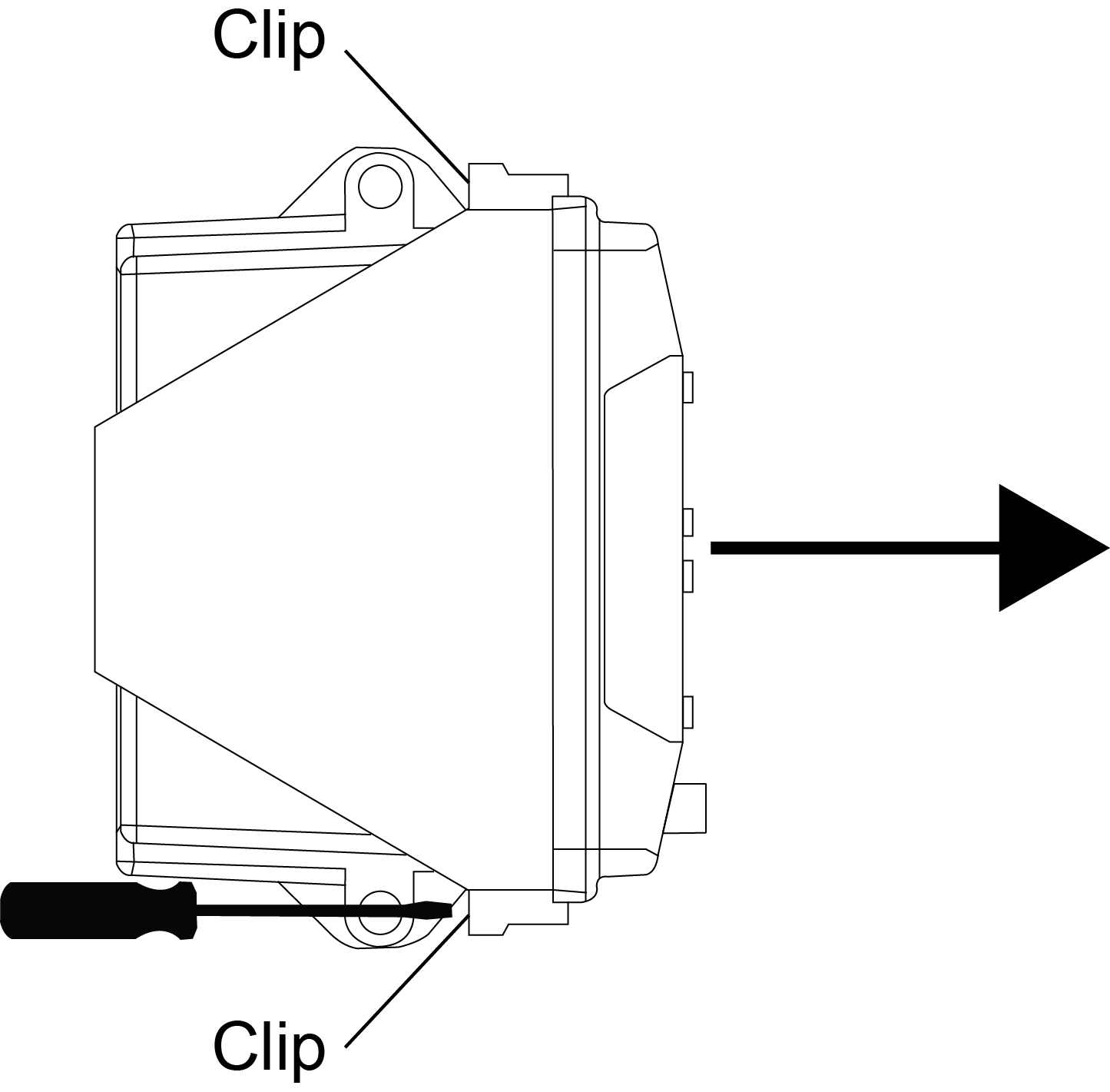
Remove the front cover to gain access to the IMU switch
The 56-pin connector and antenna cable are still connected to the interface board. |
|
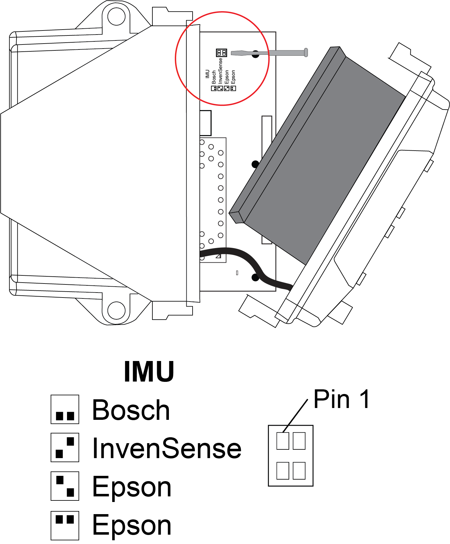
Set the IMU Switch
If installing an Epson G320N IMU, either Epson labeled DIP switch setting can be used. Setting the IMU DIP switch may be possible without entirely removing the internal interface board. The interface board must be entirely removed to install the Epson G320N IMU. See Mount the Epson G320N IMU for installation instructions for the Epson IMU. |
|
Reassemble
-
Reassemble the OEM7500 Evaluation kit.
-
Power the OEM7500 Evaluation Kit.
-
Open a communication port to the receiver.
-
Send the FRESET command to clear any existing IMU configuration settings.
-
Once the IMU resets, configure SPAN as described in SPAN setup – InvenSense IAM-20680, SPAN setup – Bosch SMI130 or SPAN setup – Epson G320N.

