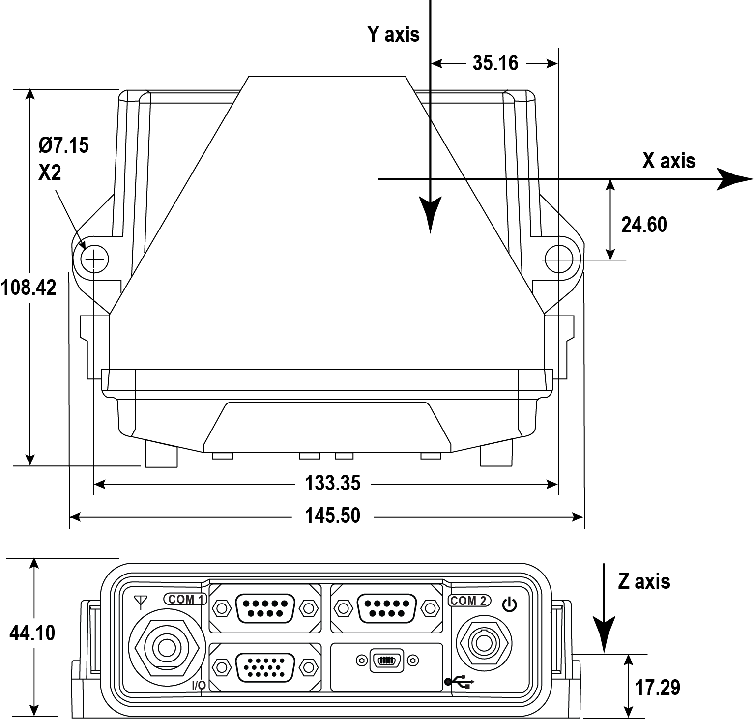
SPAN setup – Epson G320N
The Epson G320N must be mounted on the OEM7500 Evaluation Kit board before starting this procedure. See Mount the Epson G320N IMU.
It is only necessary to send the commands below if the IMU is changed or a FRESET command is sent.
To enable the SPAN functionality for the Epson G320N IMU, send the following commands:
-
SETIMUEVENT IN EVENT1
-
CONNECTIMU SPI EPSON_G320
-
SETINSPROFILE LAND
-
SETINSTRANSLATION ANT1 X Y Z [XSD] [YSD] [ZSD]
The values for X, Y and Z are the distances in metres along the X-axis, Y-axis and Z-axis, in the IMU Body frame, from the IMU center of navigation to the phase center of the primary antenna. The values for XSD, YSD and ZSD are the standard deviation values for the distances.
Large standard deviations can lead to an inaccurate position solution. Therefore, it is highly recommended to measure the translation offsets as accurately as possible and to enter translation offset standard deviations that reflect that accuracy.
-
SETINSROTATION RBV X Y Z [XSD] [YSD] [ZSD]
The values for X, Y and Z are the rotations from the IMU body frame (indicated in Figure: Epson G320N center of navigation) to the vehicle frame. The order of rotations is Z, X, Y. All rotations are right handed. The values for XSD, YSD and ZSD are the standard deviation values for the rotations.
After completing the SPAN setup, an alignment of the SPAN system must be performed. Refer to System start-up and alignment techniques for details on System Alignment. A coarse alignment cannot be used with the OEM7500 Evaluation Kit IMUs.
