SPAN setup and configuration
This section details how to setup and configure a SPAN system upon installation, INS profiles, and additional options. Setup diagram and corresponding example commands are provided to help configure IMU connection, lever arm offset, IMU Body Frame to Vehicle Frame rotation, and user defined rotation. Before diving into setup and configuration, it is important to understand the main reference frames used within SPAN on OEM7.
Reference frames
Users should be aware of three main reference frames within SPAN on OEM7: the IMU Body Frame, Vehicle Frame, and User Output Frame. Users should be aware of three main reference frames within SPAN on OEM7: the IMU Body Frame, Vehicle Frame, and User Output Frame.
The default INS output frame is dependent on the configured rotation information:
-
IMU Body Frame: If no RBV or USER rotations are configured.
-
Vehicle Frame: If the RBV rotation is configured.
-
User Output Frame: If the USER rotation is configured.
Please refer to Definition of reference frames within SPAN for more information.
IMU, vehicle and user rotation example1
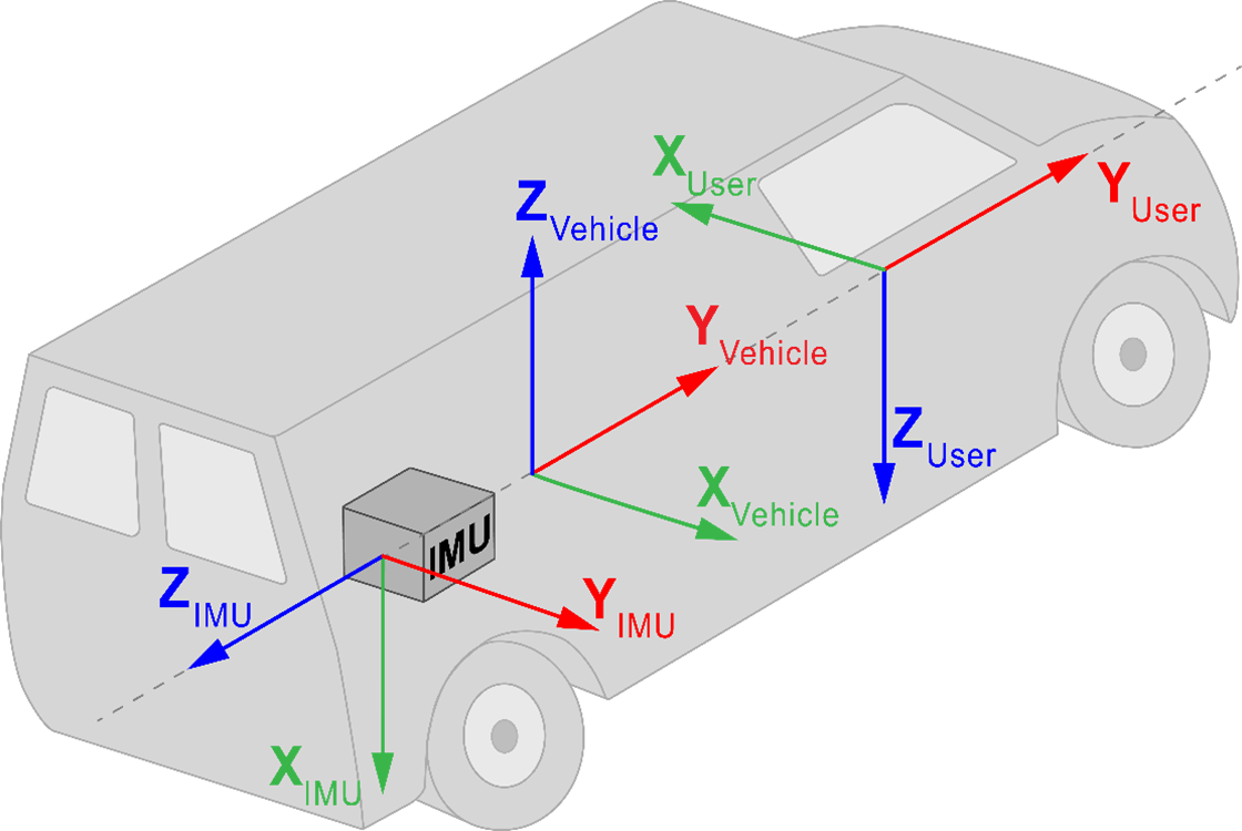
IMU body frame
The IMU Body Frame defines the orientation (reference frame) of the IMU axes marked on the IMU/enclosure. This frame will vary depending on the orientation in which the IMU is mounted.
Vehicle frame
The Vehicle Frame defines the orientation (reference frame) of the vehicle axes, defined as follows:
+X axis → towards right of vehicle
+Y axis → towards forward direction of vehicle
+Z axis → upwards
User output frame
The User Output Frame is an arbitrary frame that can be optionally defined to translate the INS position solution output location (IMU centre of navigation by default) and the INS attitude solution rotation (Local-Level frame rotated to the Vehicle frame by default).
System configuration
SPAN systems are configured either manually using commands, or using NovAtel Application Suite / NovAtel Manage Web. A correctly configured SPAN system is the first step to proper operation of an INS system and required in order to achieve desired INS system performance. When configuring your SPAN system for first time use, there are three minimum pieces of configuration information required to ensure proper operation: IMU Configuration, Lever Arm Configuration, and RBV. Along with the three minimum configurations, INS profile and other additional configurations can be used to enhance performance. Custom user defined translation and rotation configurations can also be used if desired.
IMU configuration
The CONNECTIMU command is used to specify which IMU you are connecting to and over which communication port. If you are using the internal IMU of a PwrPak7, PwrPak7D or CPT7, this step may be omitted.
Example for manual configuration:
CONNECTIMU COM2 ISA100C
Lever arm configuration
In a SPAN system, the lever arm offset is measured from the IMU centre of navigation to the L1 antenna phase centre in the IMU Body Frame or Vehicle Frame. Lever arms entered in the vehicle frame need to be aware of additional inaccuracies due to errors in the input RBV rotation, so it is recommended to have an accurate RBV configured when entering lever arms this way. Lever arm offsets measured in the IMU Body Frame are only subjected to the measurement accuracy of the lever arm itself. It is generally recommended to provide the lever arm offset in the IMU Body Frame to avoid adding uncertainty to the lever arm measurement from the RBV rotation. However, there are scenarios where measuring the lever arm in the vehicle frame may be simpler; for example, when the physical access to the line of sight of IMU axes is obstructed. Calibration of the ANT1 lever arm is an option for some IMUs (see Lever arm calibration routine).
To specify the separation from the IMU centre of navigation to the antenna phase centres, the SETINSTRANSLATION command is used. Use ANT1 for the INS Translation field to define the IMU to primary antenna lever arm and for the IMU to secondary antenna lever arm. Standard deviations entered for SETINSTRANSLATION command should reflect the actual measurement accuracy. We recommend standard deviations of 3 cm for a typical setup.
Example for manual configuration:
SETINSTRANSLATION ANT1 0.70 -1.20 0.60 0.05 0.05 0.05 IMUBODY
SETINSTRANSLATION ANT2 0.70 1.20 0.60 0.05 0.05 0.05 IMUBODY
IMU-vehicle rotation configuration (RBV)
For proper operation of a SPAN system, the rotation from the IMU Body Frame to the Vehicle Frame should be configured (known as the RBV rotation). SPAN uses a right-handed coordinate system and rotations are applied intrinsically in Z>X>Y order. Once the RBV rotation is configured, the INS output is output in the Vehicle Frame. Calibration of the RBV is an option if it’s not accurately known (see Body to vehicle frame rotation calibration routine).
To specify the rotation from the IMU Body Frame to the Vehicle Frame, the SETINSROTATION command is used. Use RBV for the INS Rotation field to define the RBV rotation. Standard deviations entered for the SETINSROTATION command should reflect the actual measurement accuracy. We recommend standard deviations of 3 degrees for a typical setup.
Example for manual configuration using Figure: IMU, vehicle and user rotation example1:
SETINSROTATION RBV -90 0 90 3 3 3
Optional custom user configurations
User translation
By default, INS position and velocity solution outputs at the IMU centre of navigation. USER translation will translate the INS solution from the IMU centre of navigation to another desired external location. To specify the offset between the IMU centre of navigation and desired external location, the SETINSTRANSLATION USER command is used.
Example for manual configuration:
SETINSTRANSLATION USER 0.70 -1.20 0.60 0 0 0 IMUBODY (translates INS solution output to antenna phase centre)
User rotation
By default, INS attitude solution outputs in the Vehicle Frame. If INS attitude solution is desired in a different reference frame than the Vehicle Frame, USER rotation will define rotation from IMU Body Frame to the desired reference frame and enable INS attitude output in the desired reference frame. Roll, pitch, and azimuth will output with respect to the Y axis rotation, X axis rotation, and Y axis direction of the desired reference frame. To specify rotation from IMU Body Frame to the desired reference frame, the SETINSROTATION USER command is used.
Example for manual configuration using Figure: IMU, vehicle and user rotation example1:
SETINSROTATION USER -90 0 -90
INS profile
INS Profiles customize some internal configuration ideal for a particular environment, including enhancing performance. Profiles currently available include:
-
DEFAULT – default SPAN profile
-
LAND – fixed axle land vehicle profile
-
MARINE – marine vessel profile
-
FIXEDWING – fixed wing aircraft profile
-
FOOT – walking or backpack application
-
VTOL – vertical take off and landing aircraft profile
-
RAIL – railway profile
-
AGRICULTURE – agriculture application profile
To specify a profile for a SPAN system, send the SETINSPROFILE command at startup. For example:
SETINSPROFILE LAND
Additional options
ALIGN – NovAtel’s dual antenna ALIGN heading technology can be used to assist the initial alignment of the SPAN solution and provide additional heading updates to the INS filter (very useful for, quick initialization requirements and/or slow/minimal rotation dynamic applications).
Relative INS – supports INS application where position, velocity and attitude vector between two SPAN systems is required.
Heave – supports short term vertical displacement of a vessel relative to the mean sea state caused by waves or swells
Variable Lever Arm – supports INS application rigidly fixed on a gimballed mount.
-
When using this feature, translation from IMU center of navigation to gimbal and rotation from the IMU body frame to the gimbal mount body frame need to be configured using SETINSTRANSLATION GIMBAL and SETINSROTATION RBM respectively.