INS initialization
Initialization is the first and most important step of all SPAN system’s real time operation; the effectiveness of this stage can have lasting impacts on the performance throughout operation. Initialization means telling the IMU where it is on the surface of the earth, and how it is oriented so that the IMU errors can be observed and accurately estimated. Initialization can be broken down into two phases, the alignment phase and the convergence phase.
INS initialization environment
The following should be followed to have a good INS initialization:
-
Ensure the IMU and antenna (or antennas) are rigidly mounted to the vehicle. The GNSS signal is received at the antenna phase centre whereas the IMU raw data and INS solution is computed at the IMU centre of navigation. The separation between IMU and antenna must therefore be constant.
-
If using a dual-antenna setup, we recommend having both antennas at constant heights, especially in applications where large pitch/roll will be experienced. Mount the IMU as close as possible to the primary antenna to maximize accuracies.
-
Mount the IMU as far as possible from external sources of vibration.
-
If INS performance is being hindered by vehicle vibrations, consider using dampening mounts to minimize vibrations. Use dampening mounts with caution as there is always a risk of removing actual motion.
-
Measure the lever arm as accurately as possible, and to a better accuracy than that of the GNSS position type accuracy (RTK, PPP, Single Point, etc.), see Lever arm calibration routine or Translational offsets for more details.
-
Ensure the antenna has clear visibility of the sky as possible.
-
If using a dual antenna setup, ensure both antennas are far from any obstructions. The GNSS-derived heading must be verified to RTK quality levels before it is fed into the INS. Being close to obstructions lengthens this process or in some cases even prevents the update from taking place.
-
If possible, start logging data as soon as possible so that complete information on INS alignment is saved.
INS alignment phase
The alignment phase is the first part of inertial initialization and is defined as the process in which the orientation of the IMU axes are determined in relation to the local level reference frame.
INS alignment methods used to initialize the SPAN INS system can be configured using the ALIGNMENTMODE command. The default ALIGNMENTMODE is AUTOMATIC. In this mode, the first available method to align is used. Sending the ALIGNMENTMODE command manually overrides the AUTOMATIC setting and changes the options available to complete an alignment.
Alignment using manual command and INS seed do not require any specific ALIGNMENTMODE configuration.
-
Static Coarse Alignment – Gyro compassing is used to determine North using only IMU measurements while stationary, no other information is required. It requires IMUs that can gyro compass (typically IMU Grade 2+). This means the IMU can sense the Earth’s rotation rate, SPAN will average the IMU raw measurements for approximately 30 - 45 seconds to acquire the initial pitch, roll and azimuth estimates.
This alignment method is enabled by:
-
ALIGNMENTMODE UNAIDED
-
ALIGNMENTMODE STATIC
-
ALIGNMENTMODE AUTOMATIC
-
-
Kinematic GNSS course over ground – North is defined by the GNSS course over ground and the IMU orientation is initialized based on the GNSS course over ground and the known RBV rotation. It must have a correct RBV rotation configured and forward motion in a straight line. Crab angles (typically observed in marine or aerial environments) will induce a bias to the kinematic alignment and should be minimized during the Kinematic Alignment routine. GNSS course over ground for three consecutive seconds is averaged provided the speed is higher than 5 m/s or the user-specified value (through the SETALIGNMENTVEL command).
This alignment method is enabled by:
-
ALIGNMENTMODE UNAIDED
-
ALIGNMENTMODE KINEMATIC
-
ALIGNMENTMODE AUTOMATIC
-
-
Dual antenna (‘Aided Transfer’) – In this case, the IMU orientation is initialized based on the computed ALIGN heading values and the known rotation between the ALIGN baseline and the IMU frame. Crab angles are no longer an issue. It requires correct ALIGN rotation configuration (ALIGN rotation is automatically calculated using primary and secondary lever arm or defined by the SETINSROTATION ALIGN command; however, it can be further calibrated using the INSCALIBRATE command).
This alignment method is enabled by:
-
ALIGNMENTMODE AIDED_TRANSFER
-
ALIGNMENTMODE AUTOMATIC
-
-
Manual command – SETINITAZIMUTH command or EXTERNALPVAS command. The user or external system is responsible for correctly supplying an initial estimate for the azimuth and appropriate confidence values. Please note this command is meant for bench test purposes OR advanced users. The initial value and its corresponding standard deviation are very important for a proper INS initialization. Using either of these commands with incorrect values and/or standard deviations (e.g., actual value has an error of 30 degrees, but user inputs a standard deviation of 1 degree) has grave repercussions on INS filter performance.
-
INS Seed – Saved and re-validated azimuths from prior operation (requires vehicle to have not moved). The IMU orientation is initialized with the orientation saved at last power off.
Convergence phase
|
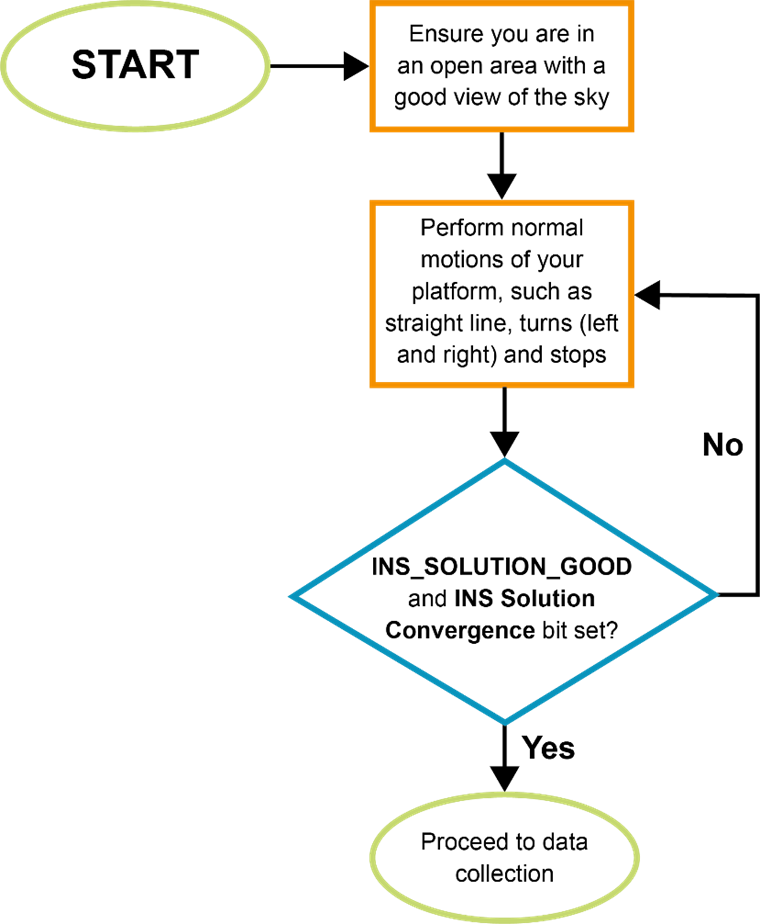
INS Alignment Procedure
|
As previously mentioned, it is very important to ensure INS alignment takes place in a relatively good GNSS environment. Right after initial INS alignment, it is necessary to insert the appropriate type of kinematics into the system to converge the bias-drift states being modelled. It is suggested to perform the following iterative process, which could take up to three minutes depending on the dynamics the platform is capable of. During this period the INS status should transition to INS_SOLUTION_GOOD and the INS Solution Convergence bit (bit 6) should update to set in the Extended Solution Status of INSPVAX log. INS filter confidence can be monitored through the INS standard deviations in the INSPVAX log. Initializing the INS and entering an urban canyon immediately after is not recommended. SPAN will not behave as per product sheet levels unless it has been properly initiated and this includes the initial kinematics. If possible, start logging data from the very beginning to ensure all information is captured should there be any issues. |