DMI connected to an IMU
|
Platform: |
OEM719, OEM729, OEM7500, OEM7600, OEM7700, OEM7720, PwrPak7 |
Prior to configuring the DMI, configure the IMU with the CONNECTIMU command.
A DMI can be connected to the following IMUs:
-
IMU-ISA-100C
-
IMU-LN200
-
IMU-HG1900
-
IMU-µIMU-IC
Figure: DMI to IMU setup shows an overview of a DMI connected to the IMU.
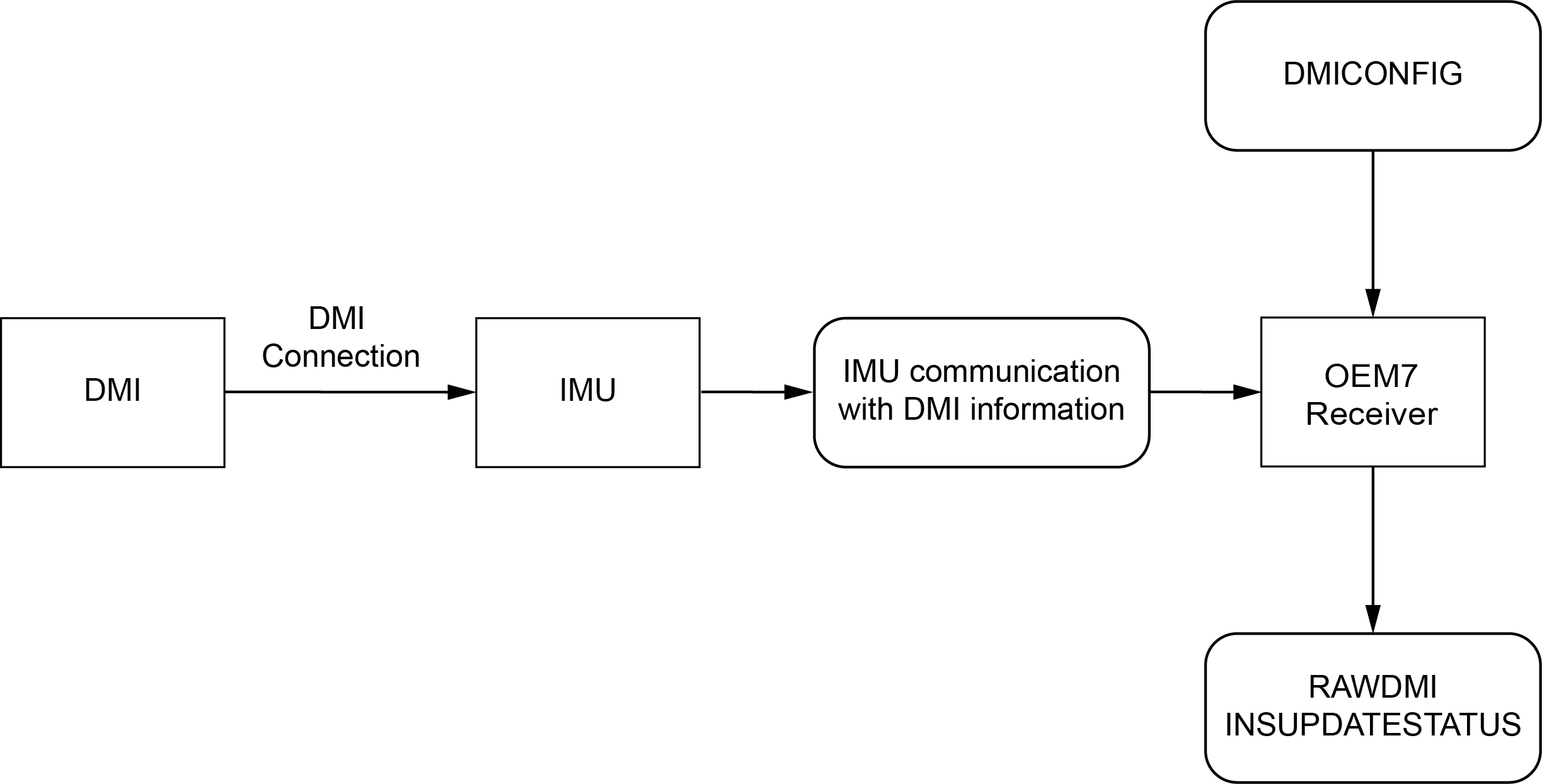
DMI data collected on IMU
Typical DMI hardware generates wheel ticks constantly as the wheel rotates. When a DMI is connected to the IMU, the wheel ticks are accumulated in the IMU. The accumulated wheel ticks, along with the raw IMU data, are sent the OEM7 receiver though the serial communication line.
DMI update logic
DMI data is available through the RAWDMI log. The RAWDMI log can be used for applying DMI updates in post-processing.
The SPAN filter uses sequential RAWDMI logs to compute a distance travelled between update intervals (1 Hz). This information is used to constrain free inertial drift during times of poor GNSS visibility. The filter also contains a state for modelling the circumference of the wheel as it may change due to hardware changes or environmental conditions.
Information about how the DMI updates are being used is available in the INSUPDATESTATUS log.
Connect the DMI to the IMU
All DMI compatible IMUs accept RS-422 differential signals from the DMI.
To connect a DMI to the IMU:
-
Install the SPAN system using the instructions in OEM7 receiver card installation or PwrPak7 installation.
-
Connect the wheel sensor to the IMU.
-
For the IMU-ISA-100C, IMU-HG1900, IMU-LN200 or IMU-µIMU-IC, use the IMU Enclosure Wheel Sensor cable (60723137), or a custom cable, to connect the DMI to the Wheel Sensor port on the IMU. See IMU Enclosure wheel sensor cable for information about the cable or for information about creating a custom wheel sensor cable.
-
-
Connect an external power supply to the DMI.
The power required for the DMI depends on the DMI used. Refer to the DMI user documents for more information.
Configure the DMI
-
Send the following command to enable a DMI on the IMU wheel sensor inputs.
DMICONFIG DMI1 ENABLE IMU
-
Send the following commands to log the DMI data.
LOG DMICONFIGA ONCHANGED
LOG RAWDMIA ONNEW
LOG INSUPDATESTATUSA ONNEW
-
Check the RAWDMI log to ensure the DMI is producing data.
-
Check the INSUPDATESTATUS log to ensure the DMI is being used in the SPAN solution.
If there is no DMI data being produced or the DMI status is not USED, refer to DMI troubleshooting.