MARKCONTROL
Controls processing of mark inputs
|
Platform: |
OEM719, OEM729, OEM7500, OEM7600, OEM7700, OEM7720, PwrPak7, CPT7, CPT7700 |
This command is used to control the processing of the mark inputs. Using this command, the mark inputs can be enabled or disabled, polarity can be changed and a time offset and guard against extraneous pulses can be added.
The MARKxPOS and MARKxTIME logs have their outputs (and extrapolated time tags) pushed into the future (relative to the mark input (MKI) event) by the amount entered into the time bias field. In almost all cases, this value is set to 0, which is also the default setting (see MARKPOS, MARK2POS, MARK3POS and MARK4POS and MARK1TIME, MARK2TIME, MARK3TIME and MARK4TIME).
Message ID: 614
Abbreviated ASCII syntax:
MARKCONTROL signal [switch [polarity [timebias [timeguard]]]]
Factory default:
MARKCONTROL MARK1 ENABLE
MARKCONTROL MARK2 ENABLE
ASCII example:
MARKCONTROL MARK1 ENABLE NEGATIVE 50 100
If using an external device, such as a camera, connect the device to the receiver’s I/O port. Use a cable that is compatible with both the receiver and the device. A MARKIN pulse can be a trigger from the device to the receiver. See also the MARKPOS, MARK2POS, MARK3POS and MARK4POS command and the MARK1TIME, MARK2TIME, MARK3TIME and MARK4TIME command.
|
Field |
Field type |
ASCII value |
Binary value |
Description |
Format |
Binary bytes |
Binary offset |
|
1 |
Command header |
- |
- |
MARKCONTROL header This field contains the command name for abbreviated ASCII or the message header for ASCII or Binary. |
- |
H |
0 |
|
2 |
signal |
MARK1 |
0 |
Specifies which mark input the command should be applied to. Set to MARK1 for the Event1 input, MARK2 for Event2, MARK3 for Event3 and MARK4 for Event4. All of the mark inputs have 10 K pull-up resistors to 3.3 V and are leading edge triggered. MARK3 and MARK4 are available only on the OEM7600, OEM7700 and OEM7720. |
Enum |
4 |
H |
|
MARK2 |
1 |
||||||
|
MARK3 |
2 |
||||||
|
MARK4 |
3 |
||||||
|
3 |
switch |
DISABLE |
0 |
Disables or enables processing of the mark input signal for the input specified. If DISABLE is selected, the mark input signal is ignored. (default = ENABLE) |
Enum |
4 |
H+4 |
|
ENABLE |
1 |
||||||
|
4 |
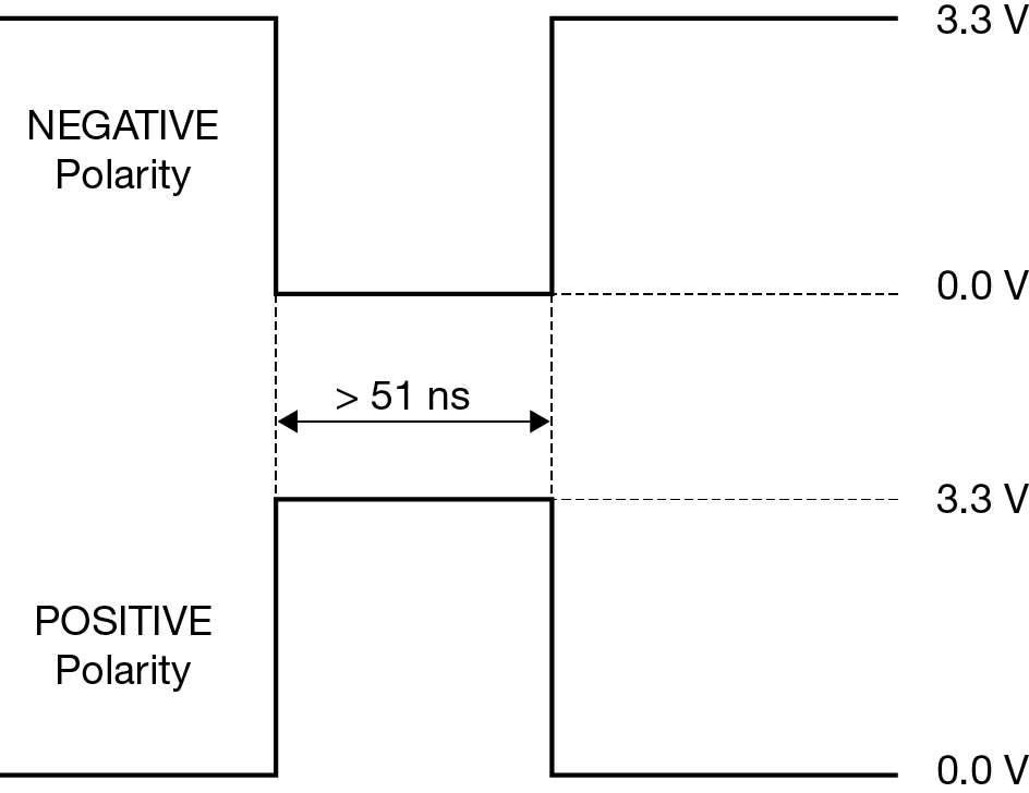
polarity |
NEGATIVE |
0 |
Optional field to specify the polarity of the pulse to be received on the mark input. See Figure: TTL pulse polarity for more information. (default= NEGATIVE) |
Enum |
4 |
H+8 |
|
POSITIVE |
1 |
||||||
|
5 |
timebias |
Any valid long value |
Optional value to specify an offset, in nanoseconds, to be applied to the time the mark input pulse occurs. (default =0) |
Long |
4 |
H+12 |
|
|
6 |
timeguard |
default: 4 Any valid Ulong value larger than the receiver’s minimum raw measurement period |
Optional field to specify a time period, in milliseconds, during which subsequent pulses after an initial pulse are ignored. See Technical specifications for the maximum raw measurement rate to determine the minimum period. If the value entered is lower than the minimum measurement period, the value is ignored and the minimum period is used. |
Ulong |
4 |
H+16 |
|