Align Options
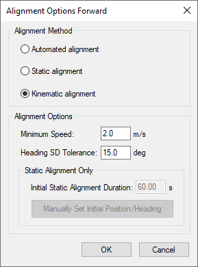
Alignment Method

Automated Alignment (Recommended)
Automated alignment scans the raw IMU data in order to determine whether a static alignment can be attempted. If no usable static alignment is detected, a kinematic alignment is applied when the vehicle reaches the minimum speed set within the auto/kinematic align tolerance. If static data is detected, a static coarse alignment is attempted for the duration of the detected session length.
Static alignment
Static alignment uses the sensed gravity vector components to estimate roll and pitch. It uses sensed Earth-rotation rate to provide an initial estimate of the yaw of the IMU. As such, only IMUs with gyro biases much less than the Earth rate (15 deg/hr at the equator) are capable of reliable static alignment.
Kinematic alignment
When no static data is detected, a kinematic alignment will be used. The GNSS Course-Over-Ground (COG) will be used as an initial approximation of the forward pointing IMU axis. As such, it is important when using a kinematic alignment that the IMU be mounted Y-forward, X-right and Z-up. If it is not possible to mount the IMU in this fashion, appropriate body to sensor rotations should be entered. If intentionally misaligning the sensor and vehicle frames, use the GNSS Heading Offset to correct the GNSS COG used in the alignment process. Kinematic alignment requires that the IMU be traveling relatively straight and level for at least 4 seconds.
Alignment Options
Minimum Speed
Specifies the minimum speed that the system must be traveling before kinematic alignment is attempted. This value should be lowered for low dynamics applications such as pedestrian surveying. Minimum speed is not considered for static alignments.
Heading SD Tolerance
Specifies the tolerance below which the heading standard deviation must fall before the alignment routine will move into navigation mode. Lower this value if the software is not achieving a good alignment. Raise this value if the software is not aligning at all. This value is tested for both static alignments and a kinematic alignments.
Initial Static Alignment Duration
Specifies the length of time the system must be stationary for static alignment. If you do not know this value you can check the GNSS velocity plot.
Manually Set Initial Position/Heading

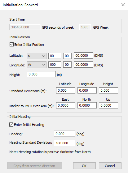
This dialog allows the user to manually set the initial position and heading for a static alignment. It is particularly useful for IMU-only processing or denied GNSS environments. The position and heading values entered should be known to a good degree of accuracy.
The Start Time will automatically be loaded depending on the start/end time in the IMR file.
The Initial Position is to be entered in DMS format with ellipsoidal height. The Standard Deviations values are mandatory. Enter small values if the accuracy of the input position is well known. The Marker to IMU Lever Arm values are optional. They are intended to be used if the unit is starting near a known point. The lever arm must be entered in the local level (ENU) frame. A compass or magnetometer may be used, for example, to determine the East and North directions.
Initial Heading is to be entered in decimal degrees along with its standard deviation. If the heading is well known, enter a small value for standard deviation. The initial heading can be gathered using a compass or magnetometer, for example.
Positive heading rotation is clockwise from North
The Copy from <opposite> direction button may be used to copy the input parameters from the opposite direction for alignment (i.e. from forward to reverse or vise versa). This is useful if the beginning and end of the survey are on an identical position and identical orientation.