Install a MIC in a standalone configuration
In a standalone configuration, the MIC is mounted separately from the OEM7 receiver.
Important! Assemble in accordance with applicable industry standards. Ensure all Electrostatic Discharge (ESD) measures are in place, in particular, use a ground strap before exposing or handling any electronic items, including the MIC, receiver and IMU. Take care to prevent damaging or marring painted surfaces, O-rings, sealing surfaces and the IMU.
For more information about ESD practices, see Electrostatic discharge (ESD) practices.
Basic MIC set up
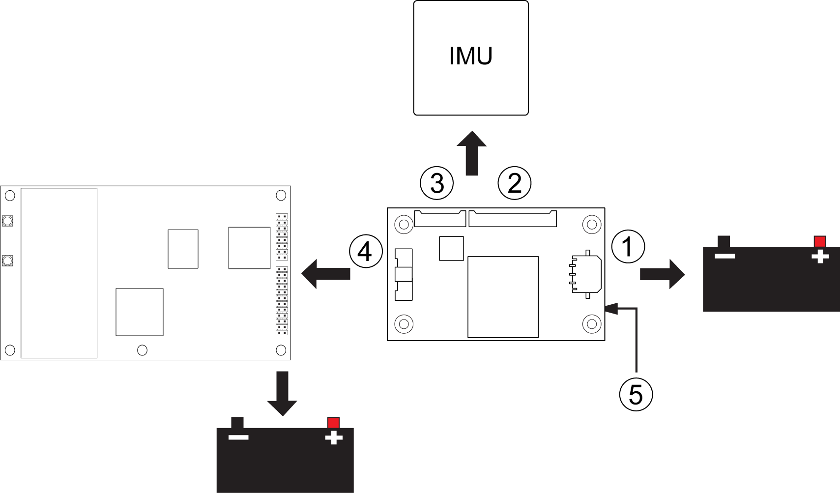
|
Ref |
Connector |
Part number |
Mating connector |
Description |
|
1 |
P101 |
43650‑0313 |
43645‑0300 |
Connects to the MIC power supply. |
|
2 |
P601 |
53780‑2070 |
51146‑2000 |
Connects to HG1700, OEM-HG1900, OEM-HG1930 and OEM-IMU-STIM300 IMUs. |
|
3 |
P701 |
53780‑1070 |
51146‑1000 |
Connects to OEM-IMU-ADIS-16488 IMUs. |
|
4 |
P301 |
501571‑3007 |
501189‑3010 |
Connects the MIC serial port to the OEM7 receiver. |
|
5 |
J301 |
ASP‑163577‑01 |
N/A |
This connector is not used. |
For information about the MIC connectors and pin-outs, see MIC connectors.
For information about the OEM7 receiver card connectors and pinouts, refer to Technical specifications.
|
|
OEM729 recommendations
|
Use the following steps to install the OEM7 receiver and MIC:
-
Mount the components of the SPAN system. See Mount the SPAN system components.
-
Connect the IMU to the MIC. See Connect the IMU to the MIC.
-
Connect the MIC to the OEM7 receiver. See Connect the MIC to a receiver.
-
Connect power to the MIC and OEM7 receiver. See Connect power to the MIC and OEM7 receiver.