Transmit (Base)

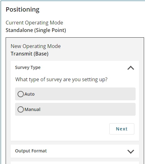
After clicking Transmit (Base) and Next, the Positioning window changes to show the Transmit options.
To configure the receiver to transmit corrections, set the parameters for Survey Type, Output Format and Output Destination.
Survey Type
The GNSS position calculated by a receiver is located at the phase center of the GNSS antenna. A receiver acting as a base station must know the location of the GNSS antenna phase center accurately to generate accurate differential correction data for the rover receiver. If the GNSS antenna is installed in a location with a well known position, use the Manual option to enter the position of the GNSS antenna phase center into the receiver. If the GNSS antenna is not installed in a well known position, use the Auto option to have the receiver calculate the antenna position.
Auto

The Auto option uses position averaging to determine the position of the GNSS antenna phase center. The position averaging starts when the Positioning configuration is applied. The position averaging continues until a specified accuracy level is met or until the specified survey time expires. When position averaging is complete, the averaged position is saved as the fix position for the base station. This fix position is then used when calculating differential corrections for the rover.
The calculated base station position is in WGS84.
On subsequent power ups or resets, the receiver uses position averaging to determine if the base station has moved. The average position calculated is compared to the saved fix position. If the average position is within tolerance, the receiver assumes it has not moved and uses the previously saved fix position. If the average position is outside of the tolerance, the receiver assumes it has moved and will continue calculating a position average until the accuracy level is met or until the specified survey time expires.
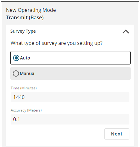
Click the Auto button to show the auto survey options.
Time
Enter the maximum amount of time allowed for the receiver to perform an automatic survey.
|
Receiver Family |
Time Range |
Default |
|---|---|---|
|
OEM7 |
1 to 6000 minutes |
1440 minutes |
Accuracy
Enter the desired horizontal standard deviation in metres. Accuracy can be a value from 0 to 100 metres. The default is 0.1 metres.
Manual

Use the Manual option to set the fix position of the base station receiver. The position entered using the Manual option should be as accurate as possible. The receiver uses this position to generate the differential correction data, so the accuracy of this position directly impacts the accuracy of the differential corrections sent to the rover receiver.
Click Manual to show the fix position options.
Latitude
Enter the latitude of the GNSS antenna phase center. The latitude can be -90 to +90 degrees where a ‘-’ sign denotes south and a ‘+’ sign denotes north.
Longitude
Enter the longitude of the GNSS antenna phase center. The longitude can be -360 to +360 degrees where a ‘-’ sign denotes west and a ‘+’ sign denotes east.
Height
Enter the height of the GNSS antenna phase center above Mean Sea Level (MSL). The height can be -1000 to +20000000 metres.
After setting the Survey Type parameters, click Next to show the Output Format parameters.
Output Format

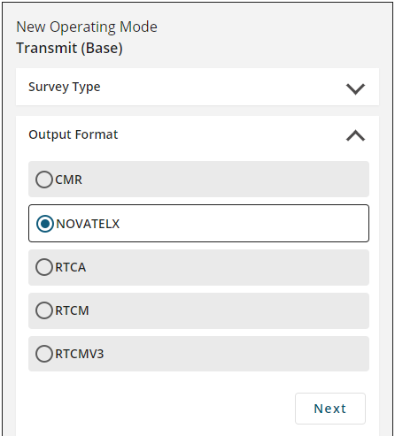
Use the Output Format parameters to set the message format the receiver uses for the differential corrections messages sent to the rover receiver.
CMR
The receiver sends differential correction messages in CMR format.
NOVATELX
The receiver sends differential correction messages in NOVATELX format.
RTCA
The receiver sends differential correction messages in RTCA format.
RTCM
The receiver sends differential correction messages in RTCM format.
RTCMV3
The receiver sends differential correction messages in RTCM Version 3.0 format.
Click the button for the message format to use and then click Next.
Output Destination

The Output Destination is the communication port, or ports, through which the receiver sends differential corrections to the rover receiver.
Serial
Click the COM buttons to select the serial ports used to send differential corrections. The number of COM ports available varies depending the type of NovAtel receiver.
When a COM button is selected, the button changes to show a settings icon. Click the settings icon to change the communication parameters used for the COM port. From the COM Configuration window that appears, set the serial communication parameters to match the parameters used by the device to which the receiver is communicating.
Baud Rate
Scroll the list of baud rates and then click a baud rate to select the communication rate (bps) used by this serial port. The default baud rate is 9600.
Parity
Click N, E or O to select the parity used by this serial port.
N = No parity, E = Even parity, O = Odd parity
The default parity is N (No Parity).
Data Bits
Click 7 or 8 to select the number of data bits used for each data message transmitted. The default is 8 bits.
Stop Bits
Click 1 or 2 to select the number of stops bits used for each data message transmitted.
After setting the communication parameters, click Done to save the new settings.
ICOM
Click the ICOM buttons to select the network ports used to send differential corrections over the receiver's Ethernet connection.
When an ICOM button is selected, the button changes to show a settings icon. Click the settings icon to change the communication parameters used for the ICOM port.
To configure an ICOM port:
-
In the Domain box, enter the hostname or IP address of the device.
-
In the Port box, enter the TCP/UDP port number used by this ICOM port.
-
Click one of the following buttons to select the protocol used by this ICOM port.
-
Disabled – Disable this ICOM port.
-
TCP – Use raw TCP on this port.
-
UDP – Use raw UDP on this port.
-
-
After setting the communication parameters, click the Done button to save the new settings.
NTRIP
Click the NCOM buttons to select the network ports used to send differential corrections. Network ports are used when the receiver is acting as an NTRIP server. The receiver must have an Ethernet connection to use NCOM ports.
When an NCOM button is selected, the button changes to show a settings icon. Click the settings icon to change the communication parameters used for the NCOM port.
To configure a NCOM port:
-
Click the Domain box and enter the hostname or IP address of the Endpoint.
-
Click the Port box and enter the TCP/UDP port number of the Endpoint.
-
Click the Search for Mountpoint button.
-
Click the Mountpoint drop menu and click on the mountpoint to use.
-
Click the Username box and enter the login user name. The username can be up to 30 characters long.
-
Click the Password box and enter the login password. The Password can be up to 30 characters long.
After setting the communication parameters, click Done to save the new settings.
File
Click the FILE button to save the differential corrections to a file.
When Output Destination ports have been selected, click Done.
When all of the Transmit parameters have been set, click Apply.
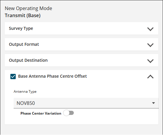
Base Antenna Phase Centre Offset

Configuring the phase center offset of the antenna used by the RTK base receiver improves RTK accuracy.
Antenna Type
There are several predefined antenna types taken from the IGS ANTEX file. To choose one of the predefined antennas, click the Antenna Type drop down menu and select the type of antenna connected to the base receiver that is providing RTK corrections.
Frequency
Select the GPS L1 check box to enter phase center offset values for the GPS L1 signal.
Select the GPS L2 check box to enter phase center offset values for the GPS L2 signal.
ARP to APC
For each frequency selected in Frequency field, enter the distance in millimetres from the Antenna Reference Point (ARP) to the Antenna Phase Center (APC).
East
Enter the East phase center offset in millimetres.
North
Enter the North phase center offset in millimetres.
Up
Enter the Up phase center offset in millimetres.
Phase Center Variation
To use the phase center variation defined for the antenna, set the switch to enabled )
)
To ignore the phase center variation defined for the antenna, set the switch to the disabled )
)