ALIGN Configuration
ALIGN technology combines two or more receivers to generate high precision heading and pitch angles between two receivers for real-time navigation.
Use the ALIGN configuration window to enable ALIGN on a dual antenna receiver or set up an ALIGN master station with an ALIGN capable rover receiver for applications that require heading output. The ALIGN configuration should be run from the ALIGN rover receiver.
Dual antenna receivers, such as the OEM7720, PwrPak7D, PwrPak7D-E1, PwrPak7D-E2 and CPT7, can provide an ALIGN solution without additional receivers or configuration.
A dual frequency capable GNSS antenna is required to use ALIGN.
Click the ALIGN tab to open the ALIGN configuration window.
The content on the ALIGN configuration window varies depending on the type of receiver and how the rover receiver is connected to the master receiver.


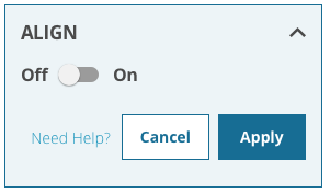
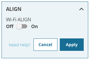
ALIGN Switch
Set the ALIGN switch to On  )
) )
)
On dual antenna receivers, the Type options appear below the ALIGN switch.
-
Click the Onboard button to calculate an ALIGN solution using the two GNSS antennas connected to the receiver.
-
Click the Serial button to use the COM2 serial port to pass ALIGN messages between the rover and master receivers.
-
Click the Wi-Fi button to use a Wi-Fi connection to pass ALIGN messages between the rover and master receivers.
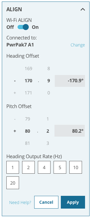
Connected to
Displays the name of the receiver with which ALIGN messages are exchanged.
To connect to a different receiver, click Change and select the master receiver to connected to.
This option is available only if a Wi-Fi connection is used to exchange ALIGN messages and the master and rover receivers are both Wi-Fi capable receivers.
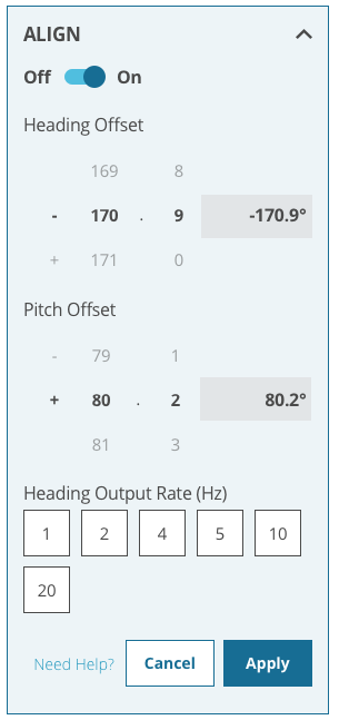
Heading Offset
Enter a value in the Heading Offset box to add an offset, in degrees, to the heading value displayed on the ALIGN status page and the heading logs (HEADING2 and GPHDT).
The receiver determines heading based on the relative location of the two GNSS antennas. This offset is used to align the heading determined by the receiver with the forward motion of the vehicle.
Pitch Offset
Enter a value in the Pitch Offset box to add an offset, in degrees, to the pitch value displayed on the ALIGN status page and the heading logs (HEADING2 and GPHDT).
The receiver determines pitch based on the relative location of the two GNSS antennas. This offset is used to align the pitch determined by the receiver with the pitch of the vehicle.
Heading Output Rate
Select one of the numbered buttons to set the rate (in Hz) at which heading data is output. The default is 10 Hz.
After setting the ALIGN parameters, click Apply to save the configuration on the receiver.