Positioning Configuration
On a PIM222A receiver, positioning configuration is applied at one time. Enter all of the applicable positioning configuration parameters, described in the following sections, and then click the Apply button.
NMEA Interface Mode
When the PIM222A COM port is in NMEA interface mode, NovAtel Application Suite is not able to retrieve the existing configuration. A message is displayed to indicate that the current configuration is not known and the parameters on the Positioning Configuration window are filled with suggested default values.
RTK
To use RTK corrections, the receiver must have a communications link through the COM2 port to an RTK base station. Use the RTK tile to configure the PIM222A to receive RTK corrections.

Input Format
Displays the format of the incoming RTK messages.
Input Port
Select the port through which RTK corrections are received.
Enable PIMTP wrapper
Select this option to receive the RTCMV3 messages that are wrapped in a PIMTP format message.
Clear this option to receive raw RTCMV3 messages.
CAN Configuration
Use the CAN Configuration tile to set the parameters the PIM222A needs to communicate on the CAN bus.

CAN Bit Rate
Select the bit rate that is used on the CAN bus to which the PIM222A is connected.
DMI Config Value
Select the DMI Config Value for the DMI connected to the PIM222A.
Please contact Hexagon A&P Application Engineering for supported DMI Configuration number details.
Vehicle Parameters
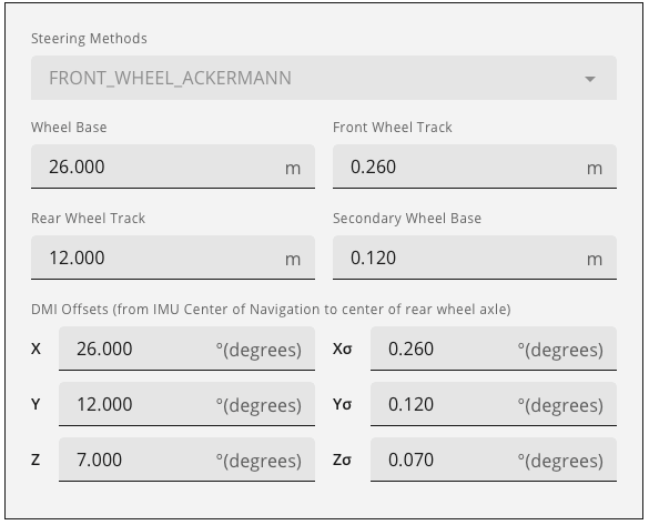
Use the Vehicle Parameters tile to set the parameters of the vehicle in which the PIM222A is installed.

Steering Methods
Click the drop down menu and select the steering method used by the vehicle.
Wheel Base
Enter the wheel base of the vehicle in metres.
Front Wheel Track
Enter the front wheel track in metres.
Rear Wheel Track
Enter the rear wheel track in metres.
Secondary Wheel Base
Enter the secondary wheel base of the vehicle in metres.
DMI Offsets
In the X, Y and Z boxes, enter the distance, in metres, from the IMU center of navigation to the center of the rear axle. The offsets are measured in three directions, X axis, Y axis and Z axis, relative to the IMU Body frame.
In the Xσ, Yσ and Zσ boxes, enter the offset standard deviation in metres. The standard deviation settings are optional.
SPAN
Use the SPAN tile to configure SPAN GNSS+INS technology on the receiver.
A dual frequency capable GNSS antenna is required to use SPAN.

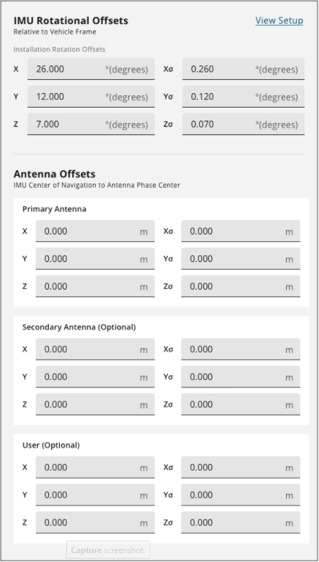
Installation Rotation Offsets
The Installation Rotations are the differences in orientation between the IMU Body Frame (typically marked on the IMU enclosure) and the vehicle frame. In the vehicle frame, Z is always considered to be upwards, Y is forward through the direction of travel, and X is to the right.
The order of rotations is Z-X-Y and all rotations are right handed.
In the X, Y and Z boxes, enter the rotations, in degrees, from the IMU Body Frame to the vehicle frame.
In the Xσ, Yσ and Zσ boxes, enter the rotation offset standard deviation. The standard deviation settings are optional.
Primary Antenna
The Primary Antenna offset is the three dimensional distance from the IMU to the primary GNSS antenna. The primary antenna offsets are required for all SPAN systems.
In the X, Y and Z boxes, enter the distance, in metres, from the IMU center of navigation to the GNSS antenna phase center. The offsets are measured in three directions, X axis, Y axis and Z axis, relative to the IMU Body frame.
In the Xσ, Yσ and Zσ boxes, enter the offset standard deviation in metres.
The measurements for the offsets should be done as accurately as possible, preferably to within millimetres especially for RTK operation. Any error in the offsets will translate into an error in the INS position.
Large standard deviations can lead to an inaccurate position solution. Therefore, it is highly recommended to measure translation offsets as accurately as possible and to manually enter translation offset standard deviations that reflect that accuracy.
Secondary Antenna
If the SPAN system has a second GNSS antenna, set the Secondary Antenna offset parameters.
In the X, Y and Z boxes, enter the distance, in metres, from the IMU center of navigation to the phase center of the secondary GNSS antenna. The offsets are measured in three directions, X axis, Y axis and Z axis, relative to the IMU Body frame.
In the Xσ, Yσ and Zσ boxes, enter the offset standard deviation in metres.
User
If the SPAN system has another device for which the relative location is needed by the SPAN system, set the User offset parameters.
In the X, Y and Z boxes, enter the distance, in metres, from the IMU center of navigation to the location of the device. The offsets are measured in three directions, X axis, Y axis and Z axis, relative to the IMU Body frame.
In the Xσ, Yσ and Zσ boxes, enter the offset standard deviation in metres. The standard deviation settings are optional.