SPAN Configuration
Use the SPAN configuration window to configure SPAN GNSS+INS technology on the receiver.
To use SPAN, the receiver must have an internal IMU (CPT7, CPT7700, PwrPak7-E1, PwrPak7D-E1, PwrPak7-E2, PwrPak7D-E2 or SMART7-S) or be connected to a SPAN compatible IMU.
A dual frequency capable GNSS antenna is required to use SPAN.
Click the SPAN tab to open the SPAN configuration window.
The SPAN configuration window shows the SPAN switch and the current SPAN configuration.
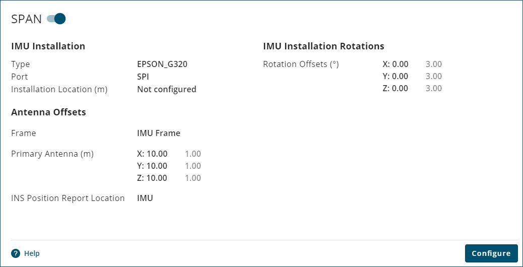
Click the SPAN switch to enable ( ) or disable (
 ) the SPAN configuration.
To change the SPAN configuration, click the Configure button. The IMU Installation window opens.
IMU Installation
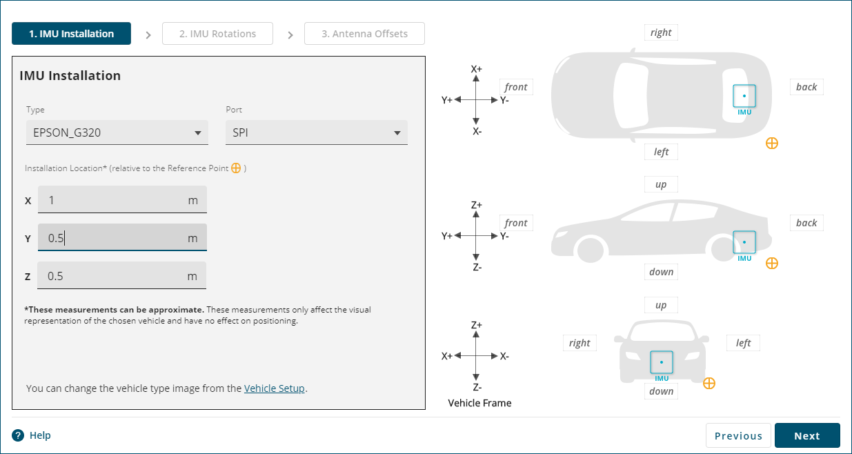
For receivers with an internal IMU (e.g. CPT7, CPT7700, PwrPak7-E1, PwrPak7D-E1, PwrPak7-E2, PwrPak7D-E2, SMART7-S), do not change the IMU Type or Port. The correct IMU Type and Port are configured at the factory.
Type
Click the Type drop menu and click on the IMU connected to the receiver.
The Vehicle Setup graphic displays after the IMU type is selected. To change the Vehicle Setup graphic or Reference point, see Vehicle Setup.
Port
Click the Port drop menu and click on the communication port to which the IMU is connected.
X
Enter the distance along the vehicle frame X axis from the Reference Point to the IMU.
Y
Enter the distance along the vehicle frame Y axis from the Reference Point to the IMU.
Z
Enter the distance along the vehicle frame Z axis from the Reference Point to the IMU.
The values entered for X, Y and Z are used only to locate the IMU on the Vehicle Setup graphic. These values are not used for the position solution.
The IMU installation location can also be changed by clicking on the IMU icon in the Vehicle Setup graphic and dragging the IMU to the correct location.
Click Next. The IMU Rotations tab opens.
IMU Rotations
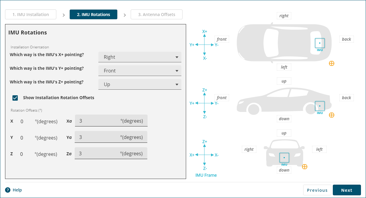
Which way is the IMU's X+ pointing?
Click the drop down menu and select the direction the X+ axis of the IMU is pointing relative to the vehicle frame (as shown in the Vehicle Setup graphic). The X+ axis of the IMU is shown on the enclosure of the IMU or receiver.
Which way is the IMU's Y+ pointing?
Click the drop down menu and select the direction the Y+ axis of the IMU is pointing relative to the vehicle frame (as shown in the Vehicle Setup graphic). The Y+ axis of the IMU is shown on the enclosure of the IMU or receiver.
Which way is the IMU's Z+ pointing?
Click the drop down menu and select the direction the Z+ axis of the IMU is pointing relative to the vehicle frame (as shown in the Vehicle Setup graphic). The Z+ axis of the IMU is shown on the enclosure of the IMU or receiver.
Only two IMU axes need to be selected. After two IMU axes are configured, NovAtel Application Suite automatically selects the correct third axis direction.
The IMU frame axes shown on the Vehicle Setup graphic are updated based on the IMU directions entered.
Show Installation Rotation Offsets
Select this option to show the IMU Rotation Offsets.
Rotation Offsets (°)
The values in the X, Y and Z boxes are the IMU Rotation Offsets, in degrees, of the current IMU rotation configuration. These values are view only.
The values in the Xσ, Yσ and Zσ boxes are the default values for the standard deviation of the IMU Rotation Offsets in degrees. These values can optionally be changed to the anticipated standard deviation values for the installation.
Click Next. The Antenna Offsets tab opens.
Antenna Offsets
For OEM7 receivers, the antenna offsets can be entered relative to the IMU frame or the vehicle frame.
Antenna Offsets in IMU Frame
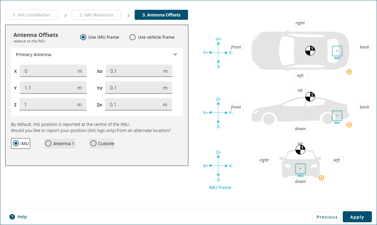
Select the Use IMU frame option to enter the antenna offsets relative to the IMU Body frame.
Primary Antenna
The Primary Antenna offset is the three dimensional distance from the IMU to the GNSS antenna. The primary antenna offsets are required for all SPAN systems.
In the X, Y and Z boxes, enter the distance, in metres, from the IMU center of navigation to the GNSS antenna phase center. The offsets are measured in three directions, X axis, Y axis and Z axis, relative to the IMU Body frame. The direction of the IMU Body frame axes are shown in the Vehicle Setup graphic.
In the Xσ, Yσ and Zσ boxes, enter the offset standard deviation in metres. The standard deviation settings are optional.
The measurements for the offsets should be done as accurately as possible, preferably to within millimetres especially for RTK operation. Any error in the offsets will translate into an error in the INS position.
Large standard deviations can lead to an inaccurate position solution. Therefore, it is highly recommended to measure translation offsets as accurately as possible and to manually enter translation offset standard deviations that reflect that accuracy.
Secondary Antenna
If the SPAN system supports two GNSS antennas, the secondary antenna offset parameters are shown.
In the X, Y and Z boxes, enter the distance, in metres, from the IMU center of navigation to the phase center of the secondary GNSS antenna. The offsets are measured in three directions, X axis, Y axis and Z axis, relative to the IMU Body frame. The direction of the IMU Body frame axes are shown in the Vehicle Setup graphic.
In the Xσ, Yσ and Zσ boxes, enter the offset standard deviation in metres. The standard deviation settings are optional.
To view the secondary antenna on the Vehicle Setup graphic, select the Show Antenna option.
Antenna Offsets in Vehicle Frame
Select the Use vehicle frame option to enter the antenna offsets relative to the vehicle frame.
Primary Antenna
The Primary Antenna offset is the three dimensional distance from the IMU to the GNSS antenna. The primary antenna offsets are required for all SPAN systems.
In the X, Y and Z boxes, enter the distance, in metres, from the IMU center of navigation to the GNSS antenna phase center. The offsets are measured in three directions, X axis, Y axis and Z axis, relative to the vehicle frame. The direction of the vehicle frame axes are shown in the Vehicle Setup graphic.
In the Xσ, Yσ and Zσ boxes, enter the offset standard deviation in metres. The standard deviation settings are optional.
The measurements for the offsets should be done as accurately as possible, preferably to within millimetres especially for RTK operation. Any error in the offsets will translate into an error in the INS position.
Large standard deviations can lead to an inaccurate position solution. Therefore, it is highly recommended to measure translation offsets as accurately as possible and to manually enter translation offset standard deviations that reflect that accuracy.
Secondary Antenna
If the SPAN system supports two GNSS antennas, the secondary antenna offset parameters are shown.
In the X, Y and Z boxes, enter the distance, in metres, from the IMU center of navigation to the phase center of the secondary GNSS antenna. The offsets are measured in three directions, X axis, Y axis and Z axis, relative to the vehicle frame. The direction of the vehicle frame axes are shown in the Vehicle Setup graphic.
In the Xσ, Yσ and Zσ boxes, enter the offset standard deviation in metres. The standard deviation settings are optional.
To view the secondary antenna on the Vehicle Setup graphic, select the Show Antenna option.
Position Center for INS Logs
The position and velocity information in the INSPVA, INSPOS, INSVEL, INSATT, and INSSPD logs, along with their short header and extended versions, can be output relative to the IMU, primary antenna, secondary antenna or a custom location.
IMU
Select this option to set center of the position and velocity information to the IMU center of navigation. IMU is the default option.
Antenna 1
Select this option to set the center of the position and velocity information to the primary GNSS antenna phase center.
Antenna 2
Select this option to set the center of the position and velocity information to the secondary GNSS antenna phase center.
Custom
Select this option to set the center of the position and velocity information to a custom location. When this option is selected, Custom offset parameters are shown.
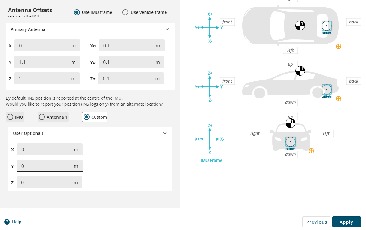
In the X, Y and Z boxes, enter the distance, in metres, from the IMU center of navigation to the custom location. The offsets are measured in three directions, X axis, Y axis and Z axis, and are relative to either the IMU Body frame (if the Use IMU frame option is selected) or the vehicle frame (if the Use vehicle frame option is selected).
The custom location is displayed on the Vehicle Setup graphic.
Click Apply to save the changes to the receiver.