DMI requirements
|
Platform: |
OEM719, OEM729, OEM7500, OEM7600, OEM7700, OEM7720, PwrPak7, CPT7, CPT7700 |
The
-
Output signal duty cycle is symmetric 40% to 60%.
-
Output signal voltage is RS-422 compliant (differential).
-
The wheel sensor is powered externally. The receiver does not supply power to the wheel sensor.
-
Quadrature, pulse and direction wheel sensors are compatible.
-
Expected maximum pulse rate over measurement range does not exceed the product-dependent limit described in Table: Wheel sensor maximum pulse rates.
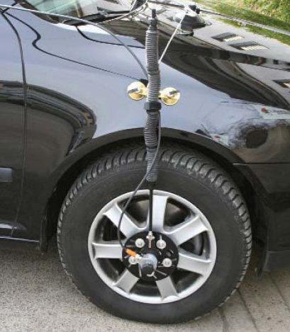
An example of a compatible DMI is the Kistler Wheel Pulse Transducer CWPTA411 (WPT). See Figure: Kistler WPT.
-
A transducer traditionally fits to the outside of a non-drive wheel. A pulse is then generated from the transducer which is fed to the receiver.
-
The WPT mounts to the wheel lug nuts via adjustable mounting collets. The torsion protection rod, which maintains rotation around the wheel axis, affixes to the vehicle body with suction cups. Refer to the Kistler WPT (part number CWPTA411) user manual for mounting instructions.
Kistler provides an M12 to DB9 cable for use with the WPT DMI. However, certain revisions of this cable do not bring through all four signal inputs. SPAN systems require at a minimum the A+ and A- signals for distance. All four signal inputs are required to measure both distance and direction correctly. See your WPT documentation for cable details.
|
Kistler cable |
PwrPak7 |
CPT7 |
IMU Enclosure |
IMU-FSAS |
||
|---|---|---|---|---|---|---|
|
M12 connector |
All I/O Cable |
IO2 Cable |
M12 Connector |
Female DB9 |
||
|
Pin |
Signal |
Wire label |
Pin on AUX 2 |
Pin |
Wire color |
Pin |
|
Pin 1 |
GND |
External |
Pin 8 |
External |
External |
|
|
Pin 2 |
+UB |
External |
||||
|
Pin 3 |
Signal A+ |
Wheel Sensor A+ |
Pin 14 |
Pin 1 |
White |
Pin 6 |
|
Pin 4 |
Signal A- |
Wheel Sensor A- |
Pin 15 |
Pin 4 |
Yellow |
Pin 7 |
|
Pin 5 |
Signal B+ |
Wheel Sensor B+ |
No connection |
Pin 2 |
Brown |
Pin 3 |
|
Pin 6 |
Signal B- |
Wheel Sensor B- |
Pin 5 |
Grey |
Pin 1 |
|
|
Pin 7 |
Reserved |
No connection |
No connection |
No connection |
No connection |
|
|
Pin 8 |
||||||
This modification is for the Kistler WPT 8-pin M12-plug cable number 14865.
The WPT requires power to operate, which is not supplied through the