Dimensions, LEDs and connectors
LEDs and connectors
|
Icon |
Name |
LED status description |
Connector description |
|---|---|---|---|
|
|
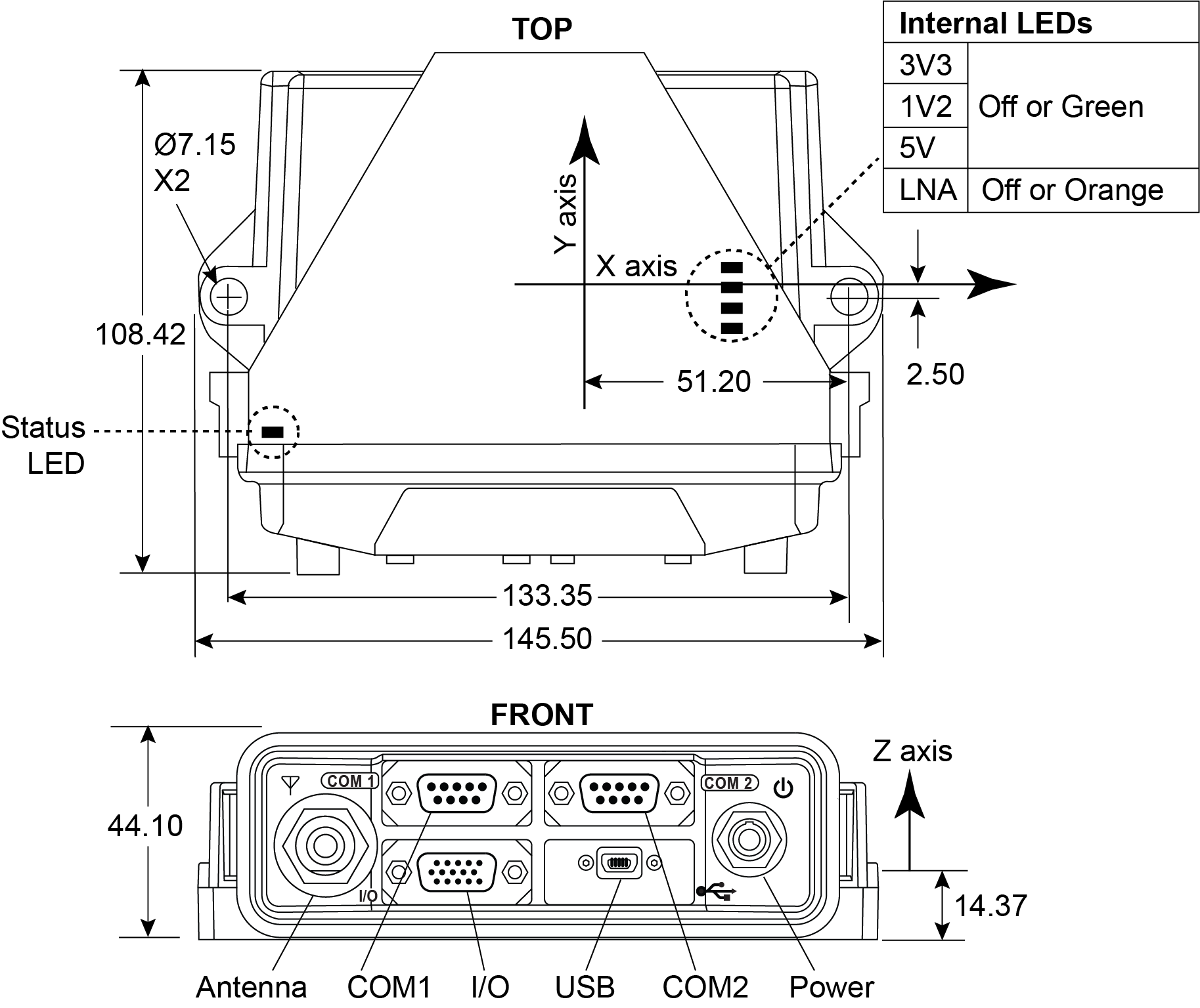
Antenna |
Solid Green – Position valid Flashing Green/Amber – Position valid and pulse per second Solid Red - Board error Flashing Red – Position not valid, |
Antenna input connector, 50 Ω nominal impedance The OEM7500 Evaluation Kit provides +5 VDC (±5%,100 mA max) to a connected antenna/LNA Connector type: TNC female jack |
|
|
Power |
Solid Red - Power on Solid Amber - Measurement Engine ready |
Valid input voltage range is +6 to +32 VDC Connector type: 4 pin Lemo |
|
|
COM1 |
Flashing Green - Transmitting data Flashing Red - Receiving data |
RS-232 serial communication port Connector type: DB9 |
|
|
COM2 |
Flashing Green - Transmitting data Flashing Red - Receiving data |
RS-232 serial communication port Connector type: DB9 |
|
|
I/O |
N/A |
Input and output port for additional signals: Connector type: DB-HD15 |
|
|
USB |
N/A |
USB communication port (USB Device) Supports USB 2.0 Full Speed (12 Mbps) Connector type: USB mini-AB |
|
|
Status |
Flashing Green = normal operation Flashing Red/Yellow = error Refer to Status LED for error status definitions. |
N/A |
