Ethernet port
OEM7 receivers, except the OEM719, provide a 10/100 Ethernet port with auto-negotiation. The Ethernet interface is disabled by default and must be configured. See the Ethernet communicationsEthernet Configuration for instructions on Ethernet device configuration. The PHY layer is based on the Texas Instruments TLK106 Ethernet PHY.
PHY terminations are provided on the OEM7 receiver card and a 3.3 V output is presented to bias the Ethernet magnetics. The 3.3 V power supplied by the OEM7 receiver card is not to be used for any purposes other than biasing the Ethernet magnetics.
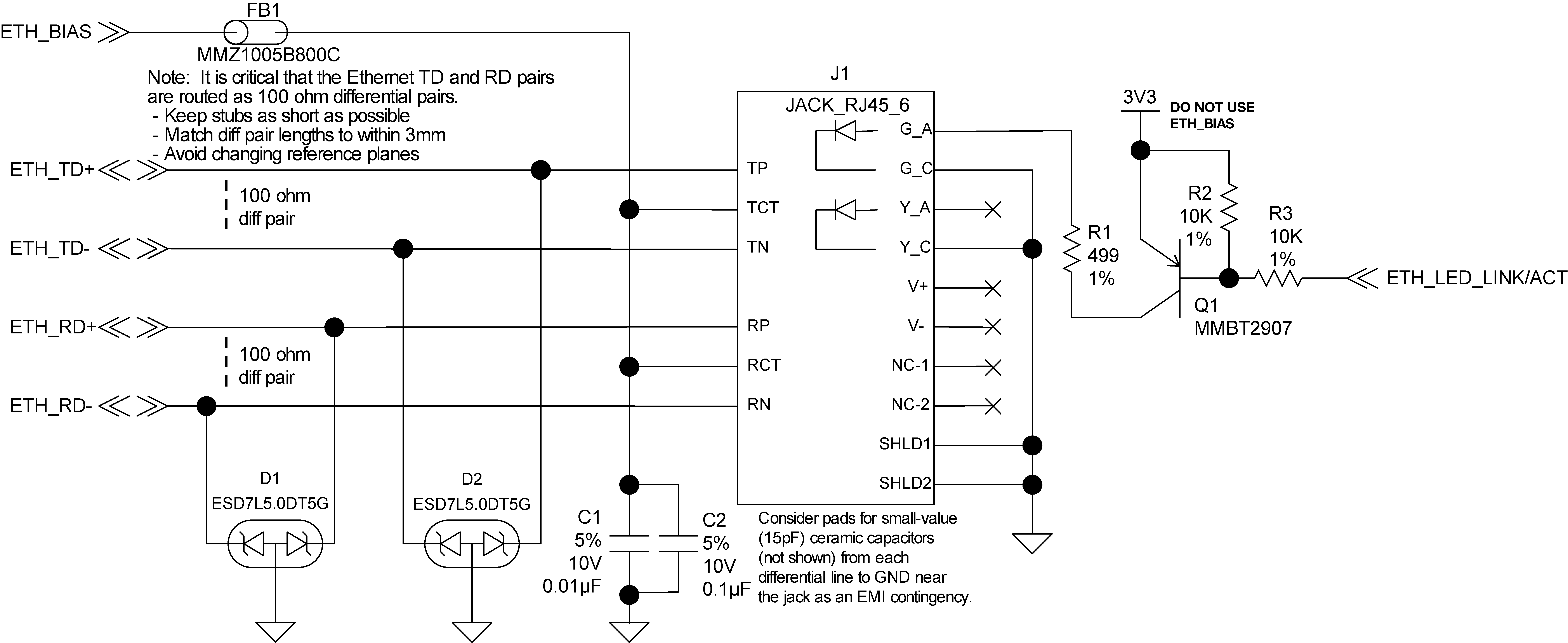
A reference schematic is shown in Figure: Ethernet reference schematic. The ferrite bead is included as an EMI de-risk contingency and may not be necessary.
|
|
OEM729 |
OEM7600 |
OEM7700 |
OEM7720 |
|---|---|---|---|---|
|
Connector |
P1803 |
P1701 |
P2001 |
P1901 |
|
ETH_BIAS |
Receive: 3 Transmit: 6 |
56 |
56 |
56 |
|
ETH_TD+ |
4 |
58 |
58 |
58 |
|
ETH_TD- |
5 |
60 |
60 |
60 |
|
ETH_RD+ |
2 |
57 |
57 |
57 |
|
ETH_RD- |
1 |
59 |
59 |
59 |
Run 100 Ω differential pairs over unbroken reference planes directly to the jack. Ensure the integrated magnetics in the jack meet the specifications in Table: Ethernet transformer characteristics. Ensure that the jack is no more than 15 cm (6 inches) from the OEM7 connector. Shorter runs are better.
|
Designator |
Manufacturer |
Manufacturer part number |
|---|---|---|
|
FB1 |
TDK |
MMZ1005B800C |
|
D1, D2 |
On Semiconductor |
ESD7L5.0DT5G |
|
J1 |
Wurth Electronics |
7499211121A |
|
Q1 |
On Semiconductor Fairchild Semiconductor |
MMBT2907ALT1G MMBT2907A |
