CAN controller ports
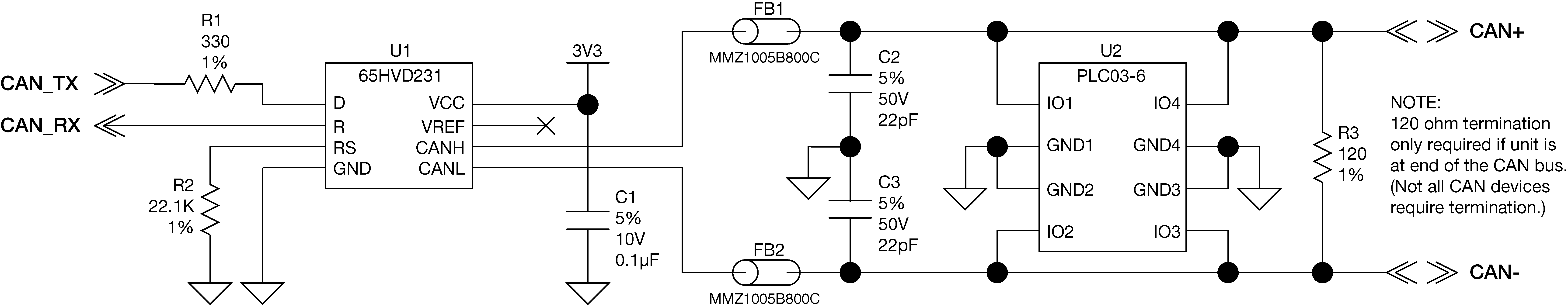
OEM7 receivers provide 3.3 V CMOS-level CAN controller ports. An external CAN transceiver is required. The following figure shows a typical CAN transceiver implementation.
The combination of ferrite beads and small-value capacitors are not necessarily required but may provide improved EMI performance. A low-capacitance TVS device is shown on the schematic to provide ESD protection.
OEM7 CAN transceiver example
|
|
OEM719 |
OEM729 |
OEM7600 |
OEM7700 |
OEM7720 |
|---|---|---|---|---|---|
|
Connector |
P17011 |
P1803 |
P1701 |
P2001 |
P1901 |
|
CAN1TX |
7 |
10 |
36 |
36 |
36 |
|
CAN1RX |
6 |
11 |
38 |
38 |
38 |
|
CAN2TX |
20 |
12 |
37 |
37 |
37 |
|
CAN2RX |
8 |
13 |
35 |
35 |
35 |
The 120Ω termination resistor should only be used when the CAN device is used at one end of the CAN bus. Multiple terminations along the length of the CAN bus will degrade performance for all CAN devices on that bus.
The slew rate adjustment resistor (R2) value shown sets the slew rate for applications for SAE J1939 agricultural applications. Other applications may require a different slew rate. Refer to the transceiver data sheet for more information.
|
Designator |
Manufacturer |
Manufacturer part number |
|
FB1, FB2 |
TDK |
MMZ1005B800C |
|
U1 |
Texas Instruments |
SN65HVD231QD |
|
U2 |
Bourns |
CDNBS08-PLC03-6 |