Install the LN-200 sensor unit
To install the LN-200 sensor unit in the Universal Enclosure:
-
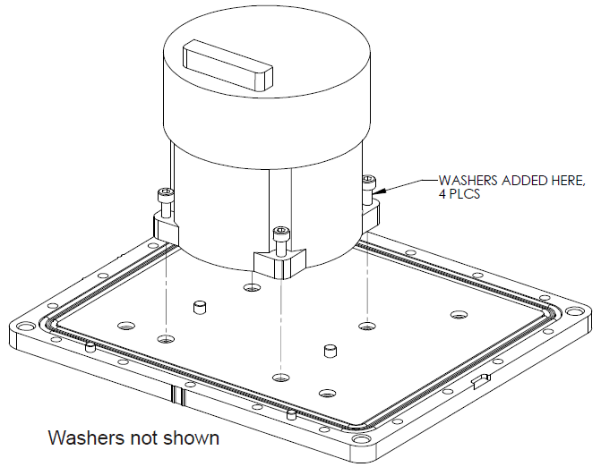
Using a 3 mm hex bit, remove original captive 6-32 screws and washers (4 each) from the LN-200 IMU. Add three washers under each of the original washers and fasten the IMU to the enclosure base, as shown in Figure: Install LN-200 IMU to base. Use thread-locking fluid on each screw.
-
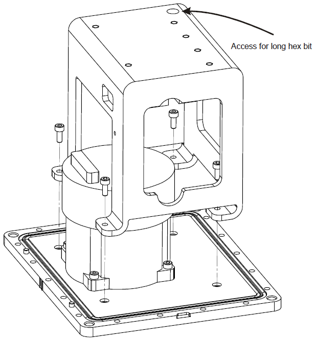
Using a long 3 mm hex bit, install the IMU bracket/SDLC to the base, as shown in Figure: Install bracket to base. Use thread-locking fluid on each M4 screw.
-
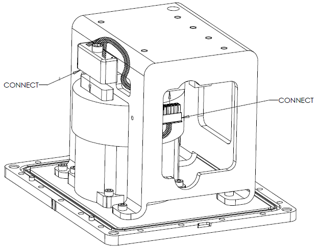
Connect the cable harness to the board assembly and IMU, routing it as shown in Figure: Making connections. Ensure latching of the cable connector housings and fasten the 6-32 screw at the IMU end using a 5/32” hex bit. Do not use thread-locking fluid and do not over tighten.
Make sure the tape of the harness is positioned for maximum protection.
-
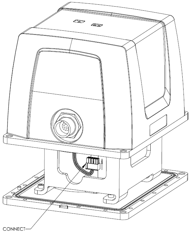
While carefully holding the body over the bracket, connect the internal cable harness to the board assembly, as shown in Figure: Connect internal cable harness.
-
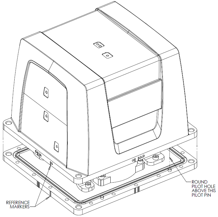
Clean the surface of the enclosure body, where it will mate with the O-rings, using isopropyl alcohol. While ensuring all wires will fit inside the bracket without being pinched, align the reference markers and pilot holes/screws of the enclosure body and base, and carefully lower the body onto the base, observing the O-rings and the alignment of corners. Start with the round pilot hole indicated in Figure: Installing the enclosure body to the base, then press the assembly into place.
-
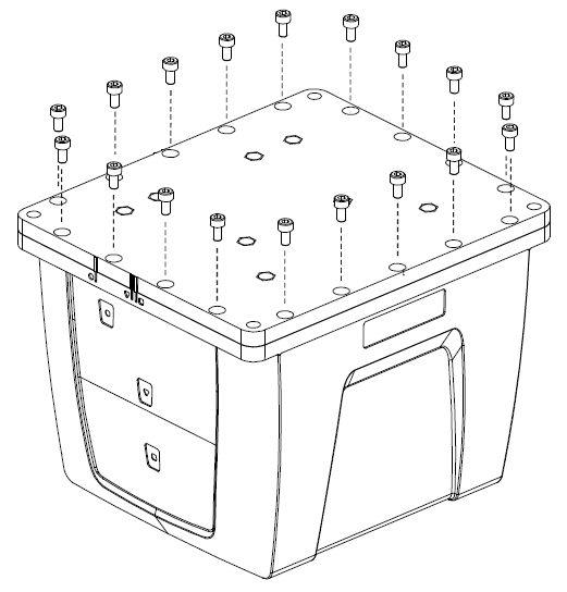
While squeezing and holding the enclosure body and base together to maintain tight contact, carefully turn the assembly over and place it on its top, as shown in Figure: Screw enclosure base to body. Using a 3 mm hex bit, lightly fasten four equally spaced M4 screws to hold the parts together. Use thread-locking fluid on all screws. Install the remaining screws in similar fashion. Tighten all screws to 1.36-1.58 N‑m (12-14 lb-in). Do not over-tighten.
-
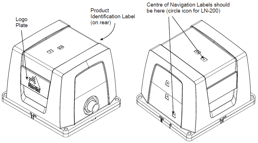
Ensure the product identification label, the logo plate and the centre of navigation labels are properly affixed and contain the correct information. The final assembled unit is shown in Figure: Final assembly.
