HEADINGOFFSET
Adds heading and pitch offset values
|
Platform: |
OEM719, OEM729, OEM7500, OEM7600, OEM7700, OEM7720, PwrPak7, CPT7, CPT7700, SMART7 |
This command is used to add an offset in the heading and pitch values of the HEADING2 log and GPHDT log.
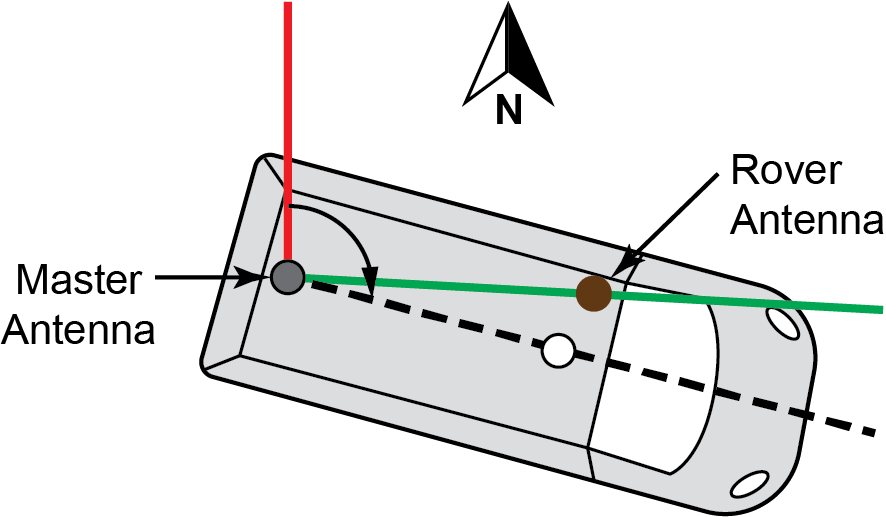
The unmodified heading value represents the angle from True North of the base to rover vector in a clockwise direction. In some installations, it may not be possible to place the rover antenna in the desired location, for instance to match the forward-facing direction of the vehicle.
HEADINGOFFSET example

In the example above, the rover antenna (in brown) is offset from the forward direction of travel and the provided heading will look as if the land vehicle is "slipping". A Heading offset can help to account for that difference between heading output and actual course over ground. It is up to the user to accurately determine the offset to be applied to suit their scenario.
HEADINGOFFSET is not required to configure Dual Antenna ALIGN with SPAN. If desired, see configuration details in Configuring dual antenna ALIGN with SPAN
Most configurations of the HEADINGOFFSET command are not compatible with Waypoint Inertial Explorer and as such is not recommended for use if the data will be post processed. Contact support (see Customer Support) for more information.
Message ID: 1082
Abbreviated ASCII syntax:
HEADINGOFFSET headingoffsetindeg [pitchoffsetindeg]
Factory default:
HEADINGOFFSET 0 0
ASCII example:
HEADINGOFFSET 2 -1
|
Field |
Field type |
ASCII value |
Binary value |
Description |
Format |
Binary bytes |
Binary offset |
|
1 |
Command header |
- |
- |
HEADINGOFFSET header This field contains the command name for abbreviated ASCII or the message header for ASCII or Binary. |
- |
H |
0 |
|
2 |
headingoffsetindeg |
-180.0 - 180.0 |
Offset added to heading output (degrees). Default=0 |
Float |
4 |
H |
|
|
3 |
pitchoffsetindeg |
-90.0 - 90.0 |
Offset added to pitch output (degrees). Default=0 |
Float |
4 |
H+4 |
|