FREQUENCYOUT
Sets output pulse train available on VARF
|
Platform: |
OEM719, OEM729, OEM7500, OEM7600, OEM7700, OEM7720, PwrPak7, CPT7, CPT7700 |
This command is used to set the output pulse train available on the Variable Frequency (VARF) or EVENT_OUT1 pin. The output waveform is coherent with the 1PPS output, see the usage note and Figure: Pulse width and 1PPS coherency.
The FREQUENCYOUT command is obsolete. Use the EVENTOUTCONTROL command to set the output pulse train on the VARF and EVENT_OUT pins.
If the CLOCKADJUST command is ENABLED and the receiver is configured to use an external reference frequency (set in the EXTERNALCLOCK command for an external clock - TCXO, OCXO, RUBIDIUM, CESIUM, or USER), then the clock steering process takes over the VARF output pins and may conflict with a previously entered FREQUENCYOUT command.
Figure: Pulse width and 1PPS coherency shows how the chosen pulse width is frequency locked but not necessarily phase locked when using ENABLE option. To synchronize the phase, use ENABLESYNC option.
The EVENTOUT outputs cannot synchronize with GPS time until the receiver reaches FINESTEERING time status. As the receiver transitions to GPS time, there may be additional, unexpected pulses on the EVENTOUT signals.
Message ID: 232
Abbreviated ASCII syntax:
FREQUENCYOUT [switch] [pulsewidth] [period]
Factory default:
FREQUENCYOUT disable
ASCII example:
FREQUENCYOUT ENABLE 50000 100000
This example generates a 50% duty cycle 1 kHz square wave.
Signal integrity will begin to degrade when generating a clock frequency greater than 10 MHz. It is not recommended to generate a clock frequency greater than 20 MHz.
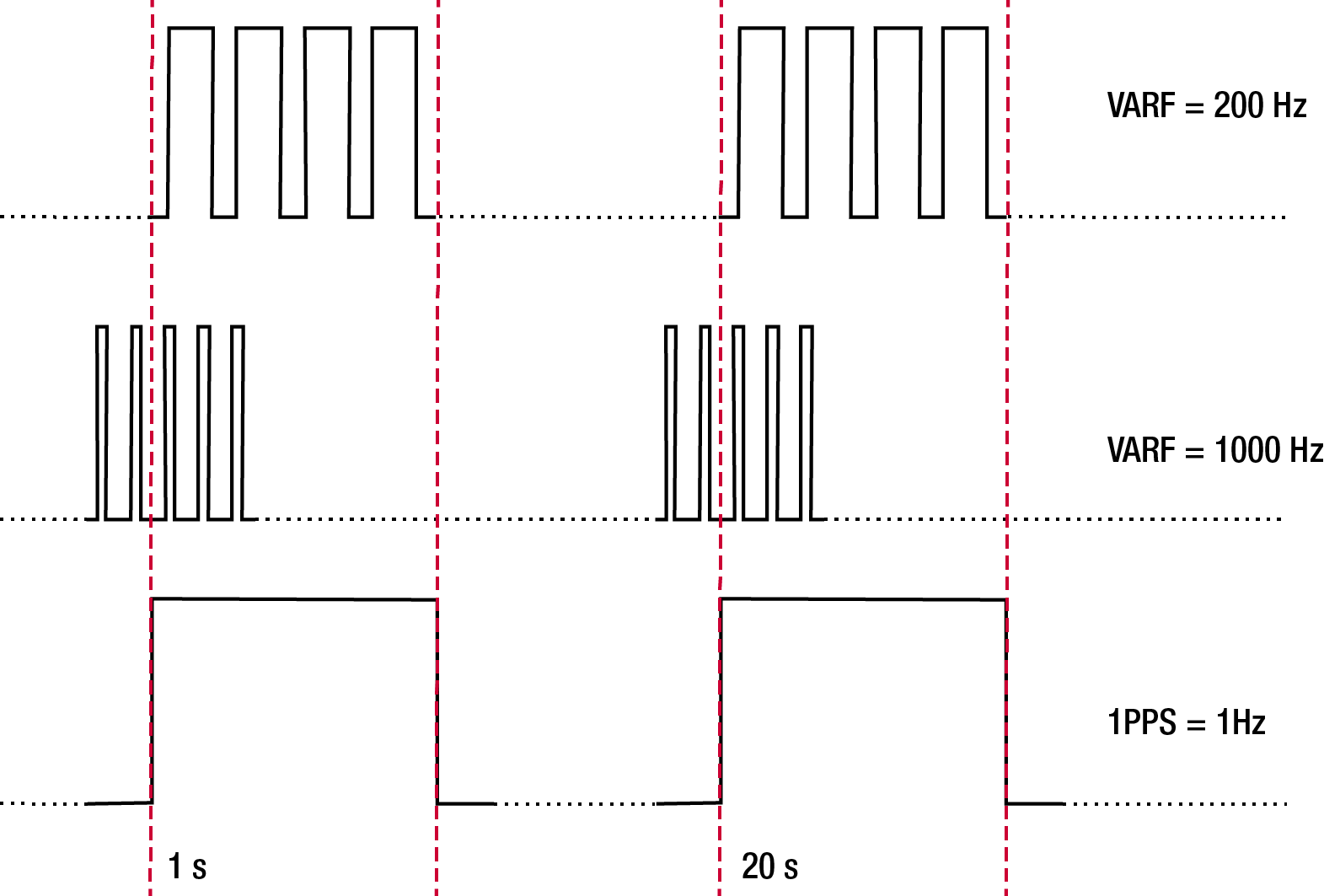
When using ENABLE option, the VARF and 1PPS are not necessarily in phase as described in Figure: Pulse width and 1PPS coherency. To align the phase of the VARF with the 1PPS, use the ENABLESYNC option and the VARF phase will be synchronized to the leading edge of the 1PPS pulse. Note that if the VARF and 1PPS frequencies are not even multiples of each other, this may cause the VARF to have a shorter cycle pulse prior to each 1PPS pulse. 1PPS is not affected.
|
Field |
Field type |
ASCII value |
Binary value |
Description |
Format |
Binary bytes |
Binary offset |
|
1 |
Command header |
- |
- |
FREQUENCYOUT header This field contains the command name for abbreviated ASCII or the message header for ASCII or Binary. |
- |
H |
0 |
|
2 |
switch |
DISABLE |
0 |
Disable causes the output to be fixed low. (if NONE specified, defaults to DISABLE) |
Enum |
4 |
H |
|
ENABLE |
1 |
Enables customized frequency output. |
|||||
|
ENABLESYNC |
2 |
Enables customized frequency output synchronized to PPS. |
|||||
|
3 |
pulsewidth |
(0 to 1073741823) |
Number of 10 ns steps for which the output is high. Duty cycle = pulsewidth / period. If pulsewidth is greater than or equal to the period, the output is a high DC signal. If pulsewidth is 1/2 the period, then the output is a square wave. (default = 0) |
Ulong |
4 |
H+4 |
|
|
4 |
period |
(0 to 1073741823) |
Signal period in 10 ns steps. Frequency Output = 100,000,000 / Period (default = 0) |
Ulong |
4 |
H+8 |
|