Example of bit parsing a RANGECMP4 log
The following takes a sample RANGECMP4 log and breaks it down into its raw components.
Data was captured in both RANGE and in RANGECMP4 logs which are shown here for reference. These logs were captured at a rate of 4 Hz such that the Reference and Differential parts of the RANGECMP4 could be explained.
Some of the RANGECMP4 values will have some very slight differences (at the millicycle level) compared to the equivalent RANGE log data due to truncating the double values into integers.
Here are two RANGE logs to reference against once the RANGECMP4 logs have been determined:
RANGE COM1 0 88.5 FINESTEERING 1919 507977.000 02000020 5103 32768
22
27 0 21761200.335 0.036 -114355879.993103 0.006 1121.758 50.0 876.785 18109c04
27 0 21761202.795 0.128 -89108485.029683 0.007 874.097 44.2 862.386 11303c0b
27 0 21761200.306 0.007 -85395622.838987 0.004 837.685 51.7 865.845 01d03c04
21 0 21214757.684 0.027 -111484302.588995 0.005 -1107.624 52.6 888.968 08109c24
21 0 21214757.049 0.122 -86870882.607297 0.006 -863.084 44.6 874.389 01303c2b
10 0 21540290.811 0.027 -113194996.162910 0.005 2288.688 52.6 889.905 08109c44
10 0 21540293.632 0.110 -88203904.731314 0.006 1783.394 45.6 868.725 01303c4b
10 0 21540289.869 0.006 -84528728.138216 0.004 1709.022 53.0 872.386 01d03c44
15 0 21776375.653 0.032 -114435625.391762 0.007 -1814.485 50.9 879.586 18109c64
15 0 21776376.038 0.129 -89170616.457446 0.007 -1413.886 44.1 862.706 11303c6b
18 0 20493192.703 0.031 -107692454.149639 0.007 212.747 51.1 891.550 08109c84
18 0 20493191.933 0.105 -83916195.494946 0.007 165.777 45.9 874.710 01303c8b
61 9 20375330.794 0.104 -108956045.737322 0.006 -3039.481 46.8 891.931 08119ca4
61 9 20375332.806 0.083 -84743599.055547 0.007 -2364.042 34.0 876.813 00b13cab
55 4 22748433.080 0.146 -121432681.638722 0.009 4061.119 43.9 416.032 18119cc4
55 4 22748438.602 0.021 -94447660.068923 0.009 3158.651 46.0 415.562 00b13ccb
38 8 19781617.845 0.058 -105744080.698106 0.004 -2024.611 51.8 893.563 18119ce4
38 8 19781623.453 0.032 -82245418.313339 0.005 -1574.698 42.2 878.833 00b13ceb
39 3 19968976.955 0.055 -106558290.405759 0.004 2248.713 52.3 875.210 08119d04
39 3 19968980.676 0.019 -82878686.553631 0.005 1749.000 46.9 870.890 00b13d0b
54 11 19507573.213 0.059 -104388964.028915 0.005 1289.410 51.8 894.613 08119d24
54 11 19507576.477 0.017 -81191427.275619 0.004 1002.874 48.0 878.832 10b13d2b
RANGE COM1 0 88.5 FINESTEERING 1919 507977.250 02000020 5103 32768
22
27 0 21761146.982 0.036 -114355599.642256 0.006 1121.140 49.9 877.035 18109c04
27 0 21761149.447 0.122 -89108266.573995 0.007 873.616 44.6 862.636 11303c0b
27 0 21761146.957 0.007 -85395413.484293 0.004 837.294 51.8 866.095 01d03c04
21 0 21214810.390 0.027 -111484579.560955 0.005 -1108.100 52.6 889.218 08109c24
21 0 21214809.754 0.120 -86871098.429369 0.005 -863.454 44.8 874.639 01303c2b
10 0 21540181.949 0.027 -113194424.080322 0.005 2288.176 52.6 890.155 08109c44
10 0 21540184.767 0.111 -88203458.952394 0.006 1782.995 45.4 868.975 01303c4b
10 0 21540181.003 0.006 -84528300.928648 0.004 1708.751 53.0 872.636 01d03c44
15 0 21776461.990 0.032 -114436079.084785 0.006 -1814.956 50.9 879.836 18109c64
15 0 21776462.375 0.129 -89170969.984233 0.007 -1414.253 44.1 862.956 11303c6b
18 0 20493182.598 0.031 -107692401.054068 0.007 212.183 51.2 891.800 08109c84
18 0 20493181.833 0.110 -83916154.122137 0.007 165.338 45.6 874.960 01303c8b
61 9 20375472.914 0.104 -108956805.696703 0.006 -3040.142 46.9 892.181 08119ca4
61 9 20375474.924 0.084 -84744190.134355 0.007 -2364.555 33.9 877.063 00b13cab
55 4 22748242.897 0.150 -121431666.427728 0.009 4060.804 43.7 416.282 18119cc4
55 4 22748248.421 0.021 -94446870.460803 0.009 3158.405 46.0 415.812 00b13ccb
38 8 19781712.549 0.059 -105744586.938646 0.004 -2025.149 51.8 893.813 18119ce4
38 8 19781718.158 0.032 -82245812.055601 0.005 -1575.117 42.3 879.083 00b13ceb
39 3 19968871.615 0.055 -106557728.318448 0.004 2248.162 52.3 875.460 08119d04
39 3 19968875.343 0.019 -82878249.374953 0.005 1748.571 46.8 871.140 00b13d0b
54 11 19507512.994 0.059 -104388641.780659 0.005 1288.778 51.7 894.863 08119d24
54 11 19507516.256 0.016 -81191176.637999 0.005 1002.383 48.1 879.082 10b13d2b
Here are the equivalent RANGECMP4 logs which will be broken down into their individual components:
#RANGECMP4A,COM1,0,88.5,FINESTEERING,1919,,02000020,fb0e,32768;295,030000421204000000009200df7688831f611fd87ca0b03a00638bbdf7b82f49b080fd0ec0ff1f091f8214ff4d4d00a1009cbf1751f6911f5141f87fd9571a96dbd7040c8090f87f0080fcf722fe9bfa8a49a8ff4f299d7f96fb9afefc771800fcffd0063f02cde01f3c7dd3ffb75240886f5fa2b0ff91f57f00003edf8b78868c882878014065dbf7d3ed6b722680d5fc0f00a4c08730fe7fecf8bffa3f003008000000002001f03fa019f8136a11273649b8fcefab9c434c7b89e71560dbfe070030b2e04fd841f33125320b80b0ecefa5ee21243ac0bb03e0ffc36a813fb13bbe5791a0f5ff9e3bdbffbb87f0cb8064f03f0000e4b67dd15bc5f4a50a3a006ca72fdee53ec86405b2c0fffa3fa450f725d5bfed7c49b1fb0fb16b45a87a9adb0740cbfe0700*8e963cf1
#RANGECMP4A,COM1,0,88.5,FINESTEERING,1919,,02000020,fb0e,32768;239,030000421204000000009200dff688831f6102005500e70162dc977c004015c07988840f6101803a805921cedf8b80002011207080e5f6351f003804081c2200be0808005c01620808725f93028057801822dae0476000a00f207180fef6251700e803401c62f3bdc8060052013009986f5f22020054004ca2053ec408005401ca8701804100000000000980ff6306fec408004801de07c8692f5102805180f721b2e04f600040152081804ef7102500600540202205fe040a0086013a0938780f61020061804e224edbdb68002010c0498030f7411d0018047812a2d47d090a004c01a609c8544f62028052006a02*c3edfd02
Reference log decoding
The RANGECMP4 log at time 507977.0 will be decoded first:
#RANGECMP4A,COM1,0,88.5,FINESTEERING,1919,507977.000,02000020,fb0e,32768;295,
030000421204000000009200df7688831f611fd87ca0b03a00638bbdf7b82f49b080fd0ec0ff1f0
91f8214ff4d4d00a1009cbf1751f6911f5141f87fd9571a96dbd7040c8090f87f0080fcf722fe9b
fa8a49a8ff4f299d7f96fb9afefc771800fcffd0063f02cde01f3c7dd3ffb75240886f5fa2b0ff9
1f57f00003edf8b78868c882878014065dbf7d3ed6b722680d5fc0f00a4c08730fe7fecf8bffa3f
003008000000002001f03fa019f8136a11273649b8fcefab9c434c7b89e71560dbfe070030b2e04
fd841f33125320b80b0ecefa5ee21243ac0bb03e0ffc36a813fb13bbe5791a0f5ff9e3bdbffbb87
f0cb8064f03f0000e4b67dd15bc5f4a50a3a006ca72fdee53ec86405b2c0fffa3fa450f725d5bfe
d7c49b1fb0fb16b45a87a9adb0740cbfe0700*7DD8F893
Since this log falls on a whole second (507977.000), it is a Reference log.
At the start of the RANGECMP4 log is the identifier for how many bytes are in the log. In this case, there are 295 bytes. The rest of the message is compressed binary data and is transmitted as LSB first so the bytes must be swapped before processing.
Reference header
The Reference Header is sent once per message. See Table: Header in the RANGECMP4 log section.
Decoding the bits starting with the first bytes:
GNSS Field (16 bits)
-
Grab the first 2 bytes (16 bits) = 0x0300
-
Swap the bytes = 0x0003
-
0x0003 in binary form = 0000 0000 0000 0011

In this example the receiver was configured to track only GPS and GLONASS systems. If other systems had been in the configuration and tracked, they would have shown here.
Reference satellite and signal block: GPS
This block is sent once for each bit set to 1 in the GNSS field (See Table: Header). As identified by the above GNSS field, the first system (right to left) is the GPS System. Use Table: Satellite and signal block to determine what satellites and signals data are contained in this GPS system:
GPS Satellites field (64 bits)
-
Grab the next 8 bytes (64 bits) = 0x0042120400000000
-
Swap the bytes = 0x0000000004124200
-
0x0000000004124200 in binary form =
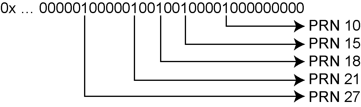
-
The 1’s above identify that there are 5 tracking GPS PRNs.
GPS Signals field (16 bits)
-
Grab the next 2 bytes (16 bits) = 0x9200
-
Swap the bytes = 0x0092
-
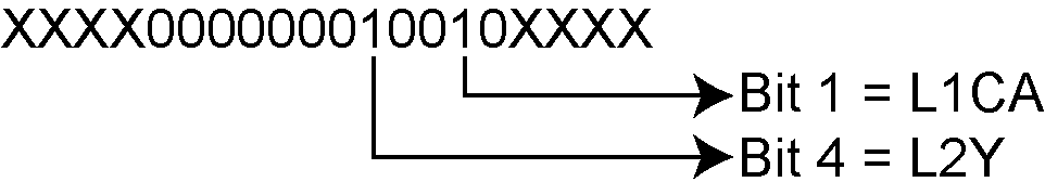
0x0092 in binary form =
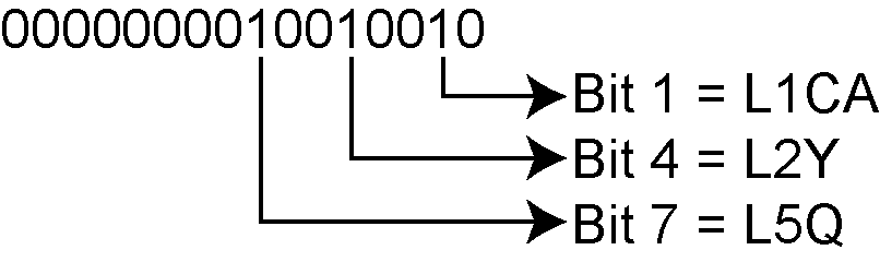
-
The 1’s above identify that there are 3 tracking GPS signals: L1CA, L2Y, and L5Q.
GPS Included Signals field (5 PRNs x 3 Signals = 15 bits – Therefore need 2 bytes)
-
Up to the point of processing the Included Signals field, the bytes are aligned such that the bits start and end within each batch of bytes. After processing this step, it is quite common for the Included Signals Field (mxn matrix) to not be divisible by 8 so bytes not processed will need to be carried over to the next section depending on the size of the matrix.
-
Grab the next 2 bytes (16 bits) = 0xdf76
-
Swap the bytes = 0x76df
-
0x76df in binary form = 0111011011011111
-
Only need 15 of the 16 bits = X111011011011111
-
This bit string breaks down into 5 rows (PRNs) and 3 columns (signals) as specified by the mxn (PRN x signals) parameters. Take the bit string and break it up into sets of 3 starting at the MSB. This will result with the lowest PRN being at the bottom row of the stack and the first signal (L1CA) being the far right column.
111
011
011
011
111
-
This stack can be further broken apart to identify the PRNs vs. their Signals:
PRN L5Q L2Y L1CA
27 1 1 1
21 0 1 1
18 0 1 1
15 0 1 1
10 1 1 1
Reference measurement block header: GPS
This block is sent once for each bit set to 1 in the Satellites field found in Table: Satellite and signal block. Now that the PRN’s signals have been determined, the next step is to determine the specifics of the first PRN (10) and its list of signals (L1CA, L2Y, L5Q). Working from bottom right to upper left of the PRN/Signal chart above, each 1 represents a signal for a PRN. Use Table: Measurement block header to determine the contents of each field:
GPS PRN 10 (first PRN found in the Satellites field)
We will grab enough bytes to process the whole Measurement Block Header. If this was a GLONASS System, a total of 9 bits would be required for this step (1 bit for the Data Format Flag, 3 bits for the Ref Data Block ID, plus 5 bits for the GLONASS Frequency Number). Since this is a GPS system, only 4 bits in total are required (1 bit for the Data Format Flag and 3 bits for the Ref Data Block ID).
There was 1 bit not processed in the last byte so that byte will be carried forward. Only 4 bits need to be looked at for this step so grab the next byte as well:
-
Use the last byte (0x76) plus the next byte (0x88)= 0x7688
-
Swap the bytes = 0x8876
-
0x8876 in binary form = 1000100001110110
-
Ignore the 7 processed bits from the last step = 100010000XXXXXXX
-
Ignore the 5 MSB bits leaving 4 bits for processing =
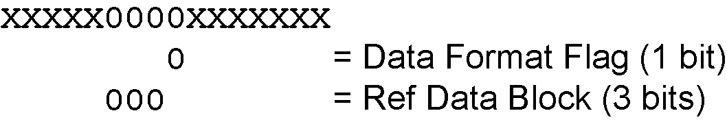
The Data Format Flag identifies that this batch of data is Reference (0) data.
The Ref Data Block ID is 0x000.
The 5 MSBs have not been processed so this byte will be carried forward.
The Data Format Flag identifies if the upcoming data is Reference or Differential data. By default every log that was published on a whole second will always be Reference logs. Logs between seconds will be Differential logs but could be Reference logs depending on the compression calculations. If a discontinuity occurred that made it impossible for a Differential calculation to fit within the Differential Constraints, it will revert to a Reference log.
Reference measurement block: GPS
This block is sent once for each bit set to 1 in the Included Signals Field found in Table: Satellite and signal block. Use Table: Primary reference signal measurement block and Table: Secondary reference signals measurement block to determine the contents of each field:
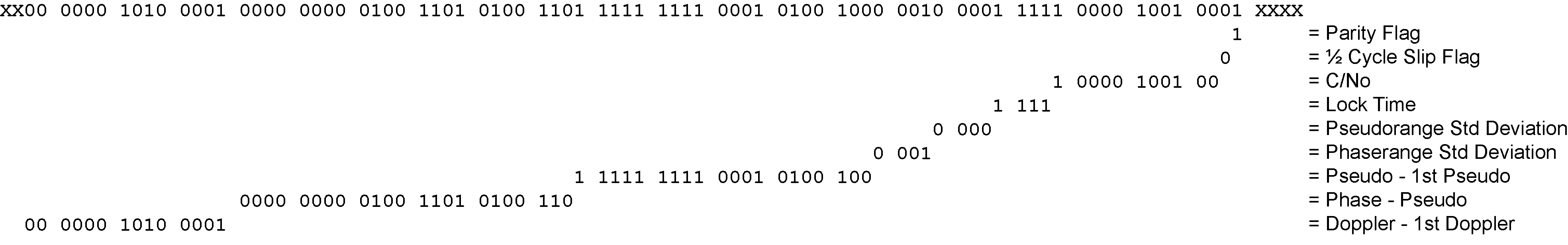
A Measurement Block for a single PRN will look like the following:
Primary Parity Flag
Primary ½ Cycle Slip Flag
Primary C/No
Primary Lock Time
Primary Pseudorange Std Deviation
Primary Phaserange Std Deviation
Primary Pseudorange
Primary Phaserange - Primary Pseudorange (determines the Phaserange for the 1st Signal)
Primary Doppler
2nd Parity Flag
2nd ½ Cycle Slip Flag
2nd C/No
2nd Lock Time
2nd Pseudorange Std Deviation
2nd Phaserange Std Deviation
2nd Pseudorange - Primary Pseudorange (determines the Pseudorange for the 2nd Signal
2nd Phaserange - 2nd Pseudorange (determines the Phaserange for the 2nd Signal)
2nd Doppler - Primary Doppler (determines the Doppler for the 2nd Signal)
3rd Parity Flag
3rd ½ Cycle Slip Flag
3rd C/No
3rd Lock Time
3rd Pseudorange Std Deviation
3rd Phaserange Std Deviation
3rd Pseudorange - Primary Pseudorange (determines the Pseudorange for the 3rd Signal
3rd Phaserange - 3rd Pseudorange (determines the Phaserange for the 3rd Signal)
3rd Doppler - Primary Doppler (determines the Doppler for the 3rd Signal)
…
Reference primary signal measurement block: GPS PRN 10 – L1CA
The next bytes collected will be for the GPS PRN 10 - L1CA signal data. This is the primary signal of the PRN since it is the first signal. As a result, its Measurement Block consists of 111 bits as listed in Table: Primary reference signal measurement block. Since 111 bits takes up a lot of space, these bits will be split into two groups from Table: Primary reference signal measurement block: the top 25 bits for signal info followed by the bottom 86 bits for signal data.
The signal info section (top 25 bits) is processed as follows:
-
With 5 bits left unprocessed from the previous byte, we calculate 25 – 5 = 20 bits which rounds up to 3 bytes. Therefore the previous last byte (0x88) plus the next 3 bytes will be needed.
-
Use the last byte (0x88) plus grab 3 bytes (x831f61) = 0x88831f61
-
Swap the bytes = 0x611f8388
-
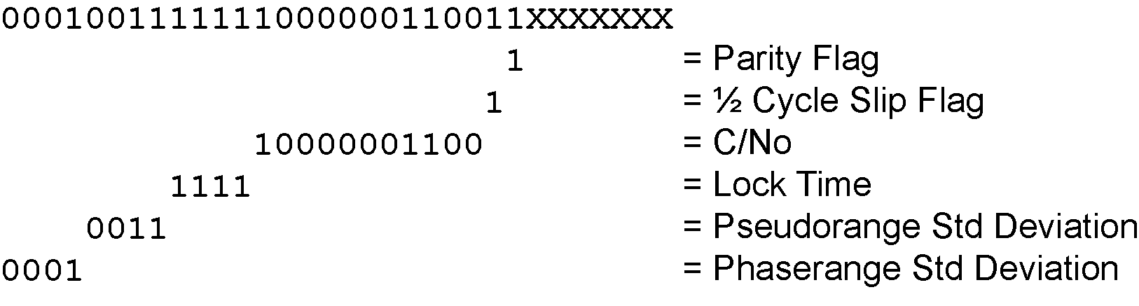
0x611f8388 in binary form = 01100001000111111000001110001000
-
The previous step used the 3 LSBs = 01100001000111111000001110001XXX
-
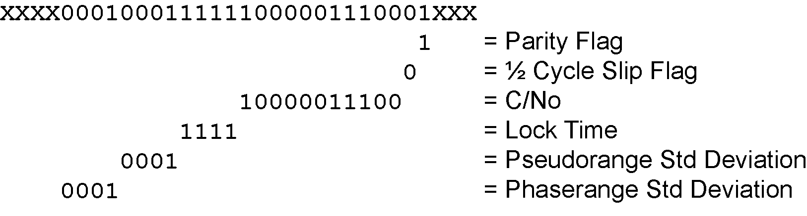
25 bits are needed so ignore the 4 MSBs =
-
-
Parity flag is a 1 (Parity Known)
-
½ Cycle Slip flag is a 0 (Cycle Slip Not Present)
-
C/No is:
0x10000011100b = 1052 x Scaling Factor of 0.05
= 52.60 dBHz -
The Lock Time value is:
0x1111b = 15 which means that this signal has been locked for 262144 ms or more. -
The Pseudorange Std Deviation value is:
0x0001b = 1 which means: 0.020 m < PSR Std Dev <= 0.030 m using Table: Pseudorange Std Dev. -
The ADR Std Deviation value is:
0x0001b = 1 which means: 0.0039 < ADR Std Dev <= 0.0052 cycles using Table: ADR Std Dev.
The signal data section (bottom 86 bits) is processed as follows:
-
With 4 bits unprocessed from the previous byte, we calculate 86 – 4 = 82 bits = 11 bytes (2 bits will not be processed in the last byte).
-
Use the last byte (0x61) plus grab 11 bytes (0x1fd87ca0b03a00638bbdf7)
= 0x611fd87ca0b03a00638bbdf7 -
Swap the bytes = 0xf7bd8b63003ab0a07cd81f61
-
0xf7bd8b63003ab0a07cd81f61 in binary form =
111 0111 1011 1101 1000 1011 0110 0011 0000 0000 0011 1010 1011 0000 1010 0000 0111 1100 1101 1000 0001 1111 0110 0001 -
Only need 86 bits. Ignore last 4 LSBs and first 6 MSBs =

-
-
Use Table: Primary reference signal measurement block to identify if a 2’s Complement Conversion is needed as well as what Scale Factor should be used before these binary numbers are used in the following calculations.
-
The 1st (Primary) Pseudorange is processed by:
1st Pseudorange = 0x0101000000111110011011000000111110110b x Scaling Factor
1st Pseudorange = 43080581622 x 0.0005
L1CA Pseudorange for PRN 10= 21540290.811 m -
The 1st (Primary) Phaserange is a 2’s Complement number (as identified by the Range column in Table: Primary reference signal measurement block) so it is processed in the following manner:
1st Phaserange – 1st Pseudorange = 2’s Complement(0x00000000001110101011000b) * Scaling Factor
1st Phaserange – 21540290.811 m = 7512 * 0.0001
L1CA Phaserange = 21540291.5622 m -
Convert this to ADR to check against the original RANGE log:
ADR = 1st Phaserange * Frequency * (-1)/Speed Of Light
ADR = 21540291.5622 m * 1575420000 Hz * (-1)/299792458 m/s
L1CA ADR for PRN 10 = -113194996.1627158 cyclesIn the range logs, PSR and ADR have opposite signs.
-
The 1st (Primary) Doppler is a 2’s Complement number (as identified by the Range column in Table: Primary reference signal measurement block) so it is processed in the following manner:
1st Doppler(m/s) = 2’s Complement(0x11101111011000101101100011b) x Scaling Factor
1st Doppler(m/s) = -4,355,229 x 0.0001
L1CA Doppler(m/s) = -435.5229 m/sConvert the Doppler to Hz:
1st Doppler(Hz) = 1st Doppler(m/s) x Frequency * (-1)/Speed Of Light
L1CA Doppler(Hz) for PRN 10 = 2288.6883 Hz
1st Doppler(Hz) = -435.5229 m/s x 1575420000 Hz * (-1)/299792458 m/s
Reference secondary signals measurement block: GPS PRN 10 – L2Y
Signal L1CA was the 1st signal (Primary Signal) of the three PRN 10 signals found in this RANGECMP4 log data. L1CA’s data is now used to determine the L2Y’s signals data. Since this is the second signal block of this PRN, its data will be processed by using Table: Secondary reference signals measurement block.
With 6 bits left unprocessed from the previous byte, we will require 82 – 6 = 76 bits which rounds up to 10 bytes.
-
Use the last byte (0xf7) plus grab the next 10 bytes (0xb82f49b080fd0ec0ff1f)
= 0xf7b82f49b080fd0ec0ff1f -
Swap the bytes = 0x1fffc00efd80b0492fb8f7
-
0x1fffc00efd80b0492fb8f7 in binary form =
0001 1111 1111 1111 1100 0000 0000 1110 1111 1101 1000 0000 1011 0000 0100 1001 0010 1111 1011 1000 1111 0111 -
Only need 78 bits. The 2 LSBs are ignored as they were already processed above and the 4 MSBs are ignored so there is a total of 82 bits to process

Use Table: Secondary reference signals measurement block to identify if a 2’s Complement Conversion is needed as well as what Scale Factor should be used before these binary numbers are used in the following calculations.
-
Parity flag is a 1 (Parity Known)
-
½ Cycle Slip flag is a 0 (Cycle Slip Not Present)
-
C/No is:
0x01110001111b = 911 x Scaling factor of 0.05
= 45.55 dBHz -
The Lock Time value is:
0x1111b = 15 which means that this signal has been locked for 262144 ms or more. -
The Pseudorange Std Deviation value is:
0x0101b = 5 which means: 0.099 m < PSR Std Dev <= 0.148 m using Table: Pseudorange Std Dev. -
The ADR Std Deviation value is:
0x0010b = 2 which means: 0.0052 < ADR Std Dev <= 0.0070 cycles using Table: ADR Std Dev. -
The L2Y Pseudorange is a 2’s Complement number (as identified by the Range column in Table: Secondary reference signals measurement block) so it is processed in the following manner:
Pseudorange – 1st Pseudorange = 2’s Complement(0x00000001011000001001b) x Scaling Factor
Pseudorange – 21540290.811 m = 5641 x 0.0005
L2Y Pseudorange = 21540293.6315 m -
The L2Y Phaserange is a 2’s Complement number (as identified by the Range column in Table: Secondary reference signals measurement block) so it is calculated in the following manner:
Phaserange – Pseudorange = 2’s Complement(0x00000000001110111111011b) * Scaling Factor
Phaserange – 21540293.6315 m = 7675 * 0.0001
L2Y Phaserange = 21540294.399 m -
Convert this to ADR to check against the original RANGE log:
ADR = Phaserange * Frequency * (-1)/Speed Of Light
ADR = 21540294.399 m * 1227600000 Hz * (-1)/299792458 m/s
L2Y ADR for PRN 10 = -88203904.73002626 cyclesIn the range logs, PSR and ADR have opposite signs.
-
The L2Y Doppler is a 2’s Complement number (as identified by the Range Column in Table: Secondary reference signals measurement block) so it is calculated in the following manner:
Doppler(m/s) – 1st Doppler(m/s) = 2’s Complement(0x11111111111111b) x Scaling Factor
Doppler(m/s) – (-435.5229 m/s) = (-1) x 0.0001
L2Y Doppler(m/s) = -435.5228 m/sConvert the Doppler to Hz:
Doppler(Hz) = Doppler(m/s) x Frequency * (-1)/Speed Of Light
Doppler(Hz) = -435.5228 m/s x 1227600000 Hz * (-1)/299792458 m/s
L2Y Doppler(Hz) for PRN 10 = 1783.3938 Hz
Reference third signals measurement block: GPS PRN 10 – L5Q
Signal L1CA was the 1st signal (Primary Signal) of the three PRN 10 signals found in this RANGECMP4 log data. L1CA’s data is now used to determine the L5Q’s signals data. Since this is the third signal block of this PRN, its data will be processed using Table: Secondary reference signals measurement block.
With 4 bits left unprocessed from the previous byte, we will require 82 – 4 = 78 bits which rounds up to 10 bytes.
-
Use the last byte (0x1f) plus grab the next 10 bytes (0x091f8214ff4d4d00a100)
= 0x1f091f8214ff4d4d00a100 -
Swap the bytes = 0x00a1004d4dff14821f091f
-
0x00a1004d4dff14821f091f in binary form =
0000 0000 1010 0001 0000 0000 0100 1101 0100 1101 1111 1111 0001 0100 1000 0010 0001 1111 0000 1001 0001 1111 -
Only need 78 bits. The 4 LSBs are ignored as they were already processed above and the 2 MSBs are ignored so there is a total of 82 bits to process
Use Table: Secondary reference signals measurement block to identify if a 2’s Complement Conversion is needed as well as what Scale Factor should be used before these binary numbers are used in the following calculations.
-
Parity flag is a 1 (Parity Known)
-
½ Cycle Slip flag is a 0 (Cycle Slip Not Present)
-
C/No is:
0x10000100100b = 1060 x Scaling Factor of 0.05
= 53.00 dBHz -
The Lock Time value is:
0x1111b = 15 which means that this signal has been locked for 262144 ms or more. -
The Pseudorange Std Deviation value is:
0x0000b = 0 which means: PSR Std Dev <= 0.020 m using Table: Pseudorange Std Dev. -
The ADR Std Deviation value is:
0x0001b = 1 which means: 0.0039 < ADR Std Dev <= 0.0052 cycles using Table: ADR Std Dev. -
The L5Q Pseudorange is a 2’s Complement number (as identified by Range column in Table: Secondary reference signals measurement block) so it is processed in the following manner:
Pseudorange – 1st Pseudorange = 2’s Complement(0x11111111100010100100b) x Scaling Factor
Pseudorange – 21540290.811 m = (-1884) x 0.0005
L5Q Pseudorange = 21540289.869 m -
The L5Q Phaserange is a 2’s Complement number (as identified by the Range column in Table: Secondary reference signals measurement block) so it is calculated in the following manner:
Phaserange – Pseudorange = 2’s Complement(0x00000000010011010100110b) * Scaling Factor
Phaserange – 21540289.869 m = 9894 * 0.0001
L5Q Phaserange = 21540290.8584 m -
Convert this to ADR to check against the original RANGE log:
ADR = Phaserange * Frequency * (-1)/Speed Of Light
ADR = 21540290.8584 m * 1176450000 Hz * (-1)/299792458 m/s
L5Q ADR for PRN 10 = -84528728.13886692 cyclesIn the range logs, PSR and ADR have opposite signs.
-
The L5Q Doppler is a 2’s Complement number (as identified by the Range column Table: Secondary reference signals measurement block) so it is calculated in the following manner:
Doppler(m/s) – 1st Doppler(m/s) = 2’s Complement(0x00000010100001b) x Scaling Factor
Doppler(m/s) – (-435.5229 m/s) = 80 x 0.0001
L5Q Doppler(m/s) = -435.5149 m/sConvert the Doppler to Hz:
Doppler(Hz) = Doppler(m/s) x Frequency * (-1)/Speed Of Light
Doppler(Hz) = -435.5149 m/s x 1176450000 Hz * (-1)/299792458 m/s
L5Q Doppler(Hz) for PRN 10 = 1709.054 Hz
This concludes the processing of the signals present for PRN 10.
The next PRN as identified in the GPS Included Signals Field is PRN 15 with 2 signals. Processing of this data would be handled as described above, starting with the 4 bit Measurement Block followed by the individual signals. This would be followed by PRN 18, 21, and 27. Processing these remaining PRNs and their signals would use up the next 870 bits as shown below:
Bits required for remaining GPS PRNs and Signals:
PRN 15
-
4 bits Measurement Block header
-
111 bits - 1st Signal
-
82 bits - 2nd Signal
PRN 18
-
4 bits Measurement Block header
-
111 bits - 1st Signal
-
82 bits - 2nd Signal
PRN 21
-
4 bits Measurement Block header
-
111 bits - 1st Signal
-
82 bits - 2nd Signal
PRN 27
-
4 bits Measurement Block header
-
111 bits - 1st Signal
-
82 bits - 2nd Signal
-
82 bits - 3rd Signal
Total = 870 bits
There are 2 bits left unprocessed from the last byte of PRN 10’s processing so 868 more bits (109 bytes) are required. After processing the remaining GPS data, there will be 4 bits left from the last byte to start off the next system (GLONASS as identified by the GNSS field in the Header).
After the last GPS bit, the GLONASS system will then be processed since it was identified as the next system by the GNSS field in the Header.
Reference satellite and signal block: GLONASS
This block is sent once for each bit set to 1 in the GNSS field found in Table: Header. As identified by the above GNSS field, the second system (right to left) is the GLONASS System. Use Table: Satellite and signal block to determine what satellites slots and signals data are contained in this GLONASS System:
GLONASS Satellites field (64 bits)
-
Grab the next 8 bytes (64 bits) = 0x3f0030080000000020
-
Swap the bytes = 0x20000000000830003f
-
0x20000000000830003f in binary form =
001000000000000000000000000000000000000000001000001100000000000000111111 -
Mask out the used 4 LSBs =
00100000000000000000000000000000000000000000100000110000000000000011XXXX -
Determine the required 64 bits =
-
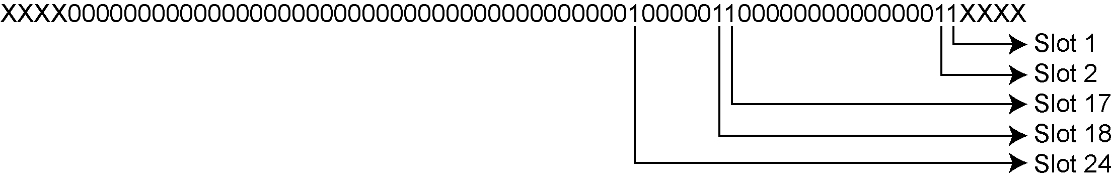
The 1’s above identify that there are 5 tracking GLONASS Slots.
-
The present GLONASS satellite PRNs/Slot ID’s (when between 1 to 24) are therefore (37 + Slot ID):
Slot 1 = PRN 38
Slot 2 = PRN 39
Slot 17 = PRN 54
Slot 18 = PRN 55
Slot 24 = PRN 61
If the GLONASS Slot ID was between 43 and 64, this would represent a GLONASS satellite that has an unknown Slot ID and is instead assigned a temporary one based upon 64 minus the unadjusted GLONASS Frequency Number (0 to 20). This Slot ID will be updated once the actual PRN/Slot ID has been determined.
GLONASS Signals field (16 bits)
-
Append the next 2 bytes (0x01f0) to the last byte (0x20) = 0x2001f0
-
Swap the bytes = 0x0f0120
-
0x0f0120 in binary form = 11110000000100100000
-
Ignore the processed bits = 1111000000010010XXXX
-
Determine the required 16 bits =
-
The 1’s above identify that there are 2 tracking GLONASS signals: L1CA and L2P.
GLONASS Included Signals field (5 Slot ID’s x 2 Signals = 10 bits)
-
Append the next byte (0x3f) to the last byte (0xf0) = 0xf03f
-
Swap the bytes = 0x3ff0
-
0x3ff0 in binary form = 0011111111110000
-
Ignore the processed bits = 001111111111XXXX
-
Determine the required 10 bits = XX1111111111XXXX
-
This bit string breaks down into 5 rows (Slots) and 2 columns (signals) as specified by the mxn (Slot IDs x signals) parameters. Take the bit string and break it up into sets of 2 starting at the MSB. This will result with the lowest Slot ID being at the bottom row of the stack and the first signal (L1CA) being the far right column.
11
11
11
11
11
-
This stack can be further broken apart to identify the Slot ID’s vs. their Signals:
SLOT L2P L1CA
24 1 1
18 1 1
17 1 1
2 1 1
1 1 1
Reference measurement block header: GLONASS PRN 38
(Slot 1 which was the first Slot found in the Satellites Field)
We will grab enough bytes to process the whole Measurement Block Header. Since this is a GLONASS System, a total of 9 bits will be required for this step (1 bit for the Data Format Flag, 3 bits for the Ref Data Block ID, plus 5 bits for the GLONASS Frequency Number).
With 2 bits left unprocessed from the previous byte, we will require 9 – 2 = 7 bits which rounds up to 1 byte:
-
Use the last byte (0x3f) plus the next byte (0xa0)= 0x3fa0
-
Swap the bytes = 0xa03f
-
0xa03f in binary form = 1010000000111111
-
Ignore the 6 processed bits from the last step = 1010000000XXXXXX
-
Ignore the 1 MSB bits leaving 9 bits for processing =
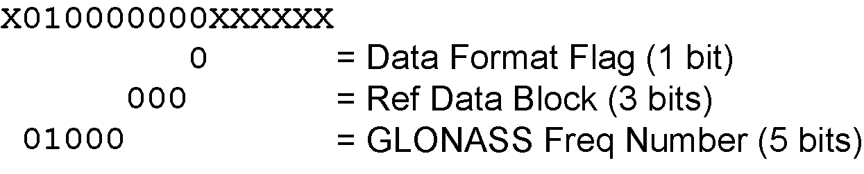
The Data Format Flag identifies that this batch of data is Reference (0) data.
The Ref Data Block ID is 0x000.
The GLONASS Frequency Number is 8 (adjusted to 1). When calculating the GLONASS Carrier frequency, this value (0 to 20) will be adjusted to its -7 to +13 value and then multiplied by that frequencies delta. Note that this field only appears in the Reference data and will not be found in the Differential data.
Special Case: When the Slot ID is between 43 and 63, the Slot ID of the GLONASS satellite is unknown. In order to keep track of which satellite it is for these calculations, the Frequency Number is used to assign this GLONASS Satellite a temporary Slot ID based on the GLONASS Frequency Numbers binary value of 0 to 20.
Reference primary signal measurement block: GLONASS PRN 38 – L1CA
The next bytes collected will be for the GLONASS PRN 38 - L1CA signal data. This is the primary signal of the satellite since it is the first signal. As a result, its Measurement Block consists of 111 bits as listed in Table: Primary reference signal measurement block. Since 111 bits takes up a lot of space, these bits will be split into two groups from Table: Primary reference signal measurement block: the top 25 bits for signal info followed by the bottom 86 bits for signal data.
The signal info section (top 25 bits) is processed as follows:
-
With 1 bit left unprocessed from the previous byte, we calculate 25 – 1 = 24 bits which equals 3 bytes. Therefore the previous last byte (0xa0) plus the next 3 bytes will be needed.
-
Use the last byte (0xa0) plus grab 3 bytes (x19f813) = 0xa019f813
-
Swap the bytes = 0x13f819a0
-
0x13f819a0 in binary form = 00010011111110000001100110100000
-
The previous step used the 7 LSBs = 0001001111111000000110011XXXXXXX
-
Need 25 bits which is exactly what is left over:
-
-
Parity flag is a 1 (Parity Known)
-
½ Cycle Slip flag is a 1 (Cycle Slip Present)
-
C/No is:
0x10000001100b = 1036 x Scaling factor of 0.05
= 51.80 dBHz -
The Lock Time value is:
0x1111b = 15 which means that this signal has been locked for 262144 ms or more. -
The Pseudorange Std Deviation value is:
0x0011b = 3 which means: 0.045 m < PSR Std Dev <= 0.066 m using Table: Pseudorange Std Dev. -
The ADR Std Deviation value is:
0x0001b = 1 which means: 0.0039 < ADR Std Dev <= 0.0052 cycles using Table: ADR Std Dev.
The signal data section (bottom 86 bits) is processed as follows:
-
With no unprocessed bits from the previous byte, we need 86 bits which rounds up to 11 bytes.
-
Grab 11 bytes = 0x6a11273649b8fcefab9c43
-
Swap the bytes = 0x439cabeffcb8493627116a
-
0x439cabeffcb8493627116a in binary form =
0100 0011 1001 1100 1010 1011 1110 1111 1111 1100 1011 1000 0100 1001 0011 0110 0010 0111 0001 0001 0110 1010
-
Only need 86 bits. Ignore first 2 MSBs =

-
-
Use Table: Primary reference signal measurement block to identify if a 2’s Complement Conversion is needed as well as what Scale Factor should be used before these binary numbers are used in the following calculations.
-
The 1st (Primary) Pseudorange is processed by:
1st Pseudorange = 0x0100100110110001001110001000101101010b x Scaling Factor
1st Pseudorange = 39563235690 x 0.0005
L1CA Pseudorange for PRN 38 = 19781617.845 m -
The 1st (Primary) Phaserange is a 2’s Complement number (as identified by the Range column in Table: Primary reference signal measurement block) so it is processed in the following manner:
1st Phaserange – 1st Pseudorange = 2’s Complement(0x11111111110010111000010b) * Scaling Factor
1st Phaserange – 19781617.845 m = -6718 * 0.0001
L1CA Phaserange = 19781617.1732 m -
Convert this to ADR to check against the original RANGE log:
ADR = 1st Phaserange * (Carrier Frequency + Frequency Number * 562500 Hz) * (-1)/Speed Of Light
ADR = 19781617.1732 m * (1602000000 Hz + 1 * 562500 Hz) * (-1)/299792458 m/s
ADR = 19781617.1732 m * 1602562500 Hz * (-1)/299792458 m/s
L1CA ADR for PRN 38 = -105744080.6970745 cyclesIn the range logs, PSR and ADR have opposite signs.
-
The 1st (Primary) Doppler is a 2’s Complement number (as identified by the Range column in Table: Primary reference signal measurement block) so it is processed in the following manner:
1st Doppler(m/s) = 2’s Complement(0x00001110011100101010111110b) x Scaling Factor
1st Doppler(m/s) = 3787454 m/s x 0.0001
L1CA Doppler(m/s) = 378.7454 m/sConvert the Doppler to Hz:
1st Doppler(Hz) = 1st Doppler(m/s) x (Carrier Frequency + Frequency Number * 562500 Hz) * (-1)/Speed Of Light
1st Doppler(Hz) = 378.7454 m/s x (1602000000 Hz + 1 * 562500 Hz) * (-1)/299792458 m/s
1st Doppler(Hz) = 378.7454 m/s x 1602562500 Hz * (-1)/299792458 m/s
L1CA Doppler(Hz) for PRN 38 = -2024.6112 Hz
The rest of the GLONASS Reference Signals are handled in a similar manner as described in the above GPS section.
Differential log decoding
Logs not falling on a whole second are most likely Differential logs which are processed differently than the Reference logs. It is possible for a sub-second RANGECMP4 log to be a Reference log if the data contained within it did not fit the tight Differential Compression requirements.
Differential logs use the reference data of the same signal unlike reference logs which uses the first signal to define the other signals.
The next RANGECMP4 log is at time 507977.250:
#RANGECMP4A,COM1,0,88.5,FINESTEERING,1919,507977.250,02000020,fb0e,32768;239,
030000421204000000009200dff688831f6102005500e70162dc977c004015c07988840f6101803
a805921cedf8b80002011207080e5f6351f003804081c2200be0808005c01620808725f93028057
801822dae0476000a00f207180fef6251700e803401c62f3bdc8060052013009986f5f220200540
04ca2053ec408005401ca8701804100000000000980ff6306fec408004801de07c8692f51028051
80f721b2e04f600040152081804ef7102500600540202205fe040a0086013a0938780f610200618
04e224edbdb68002010c0498030f7411d0018047812a2d47d090a004c01a609c8544f6202805200
6a02*48E189A2
At the start of the RANGECMP4 log is the identifier for how many bytes are in the log. In this case, there are 239 bytes (just under 20% less than a Reference Log). The rest of the message is compressed binary data and is transmitted as LSB first so the bytes must be swapped before processing.
Differential header
The Differential Header is sent once per message (See Table: Header).
Decoding the bits starting with the first bytes:
GNSS field (16 bits)
-
Grab the first 2 bytes (16 bits) = 0x0300
-
Swap the bytes = 0x0003
-
0x0003 in binary form =
In this example the receiver was configured to track only GPS and GLONASS systems. If other systems had been in the configuration and tracked, they would have shown here.
Differential satellite and signal block
This block is sent once for each bit set to 1 in the GNSS field found in Table: Header. As identified by the above GNSS field, the first system (right to left) is the GPS System. Use Table: Satellite and signal block to determine what satellites and signals data are contained in this GPS System:
GPS Satellites field (64 bits)
-
Grab the next 8 bytes (64 bits) = 0x0042120400000000
-
Swap the bytes = 0x…0000000004124200
-
0x0000000004124200 in binary form =
-
The 1’s above identify that there are 5 tracking GPS PRNs.
GPS Signals field (16 bits)
-
Grab the next 2 bytes (16 bits) = 0x9200
-
Swap the bytes = 0x0092
-
0x0092 in binary form =
-
The 1’s above identify that there are 3 tracking GPS signals: L1CA, L2Y, and L5Q.
GPS Included Signals field (5 PRNs x 3 Signals = 15 bits – therefore need 2 bytes)
Up to the point of processing the Included Signals field, the bytes are aligned such that the bits start and end within each batch of bytes. After processing this step, it is quite common for the Included Signals field (mxn matrix) to not be divisible by 8 so bytes not processed will need to be carried over to the next section depending on the size of the matrix.
-
Grab the next 2 bytes (16 bits) = 0xdff6
-
Swap the bytes = 0xf6df
-
0xf6df in binary form = 1111011011011111
-
Only need 15 of the 16 bits = X111011011011111
-
This bit string breaks down into 5 rows (PRNs) and 3 columns (signals) as specified by the mxn (PRN x signals) parameters. Take the bit string and break it up into sets of 3 starting at the MSB. This will result with the lowest PRN being at the bottom row of the stack and the first signal (L1CA) being the far right column.
111
011
011
011
111
-
This stack can be further broken apart to identify the PRNs vs. their Signals:
PRN L5Q L2Y L1CA
27 1 1 1
21 0 1 1
18 0 1 1
15 0 1 1
10 1 1 1
Differential measurement block header
This block is sent once for each bit set to 1 in the Satellites field found in Table: Satellite and signal block. Now that the PRN’s signals have been determined, the next step is to determine the specifics of the first PRN (10) and its list of signals (L1CA, L2Y, L5Q). Working from bottom right to upper left of the PRN/Signal chart above, each 1 represents a signal for a PRN. Use Table: Measurement block header to determine the contents of each field:
GPS PRN 10 (first PRN found in the Satellites field)
We will grab enough bytes to process the whole Measurement Block Header. If this was a GLONASS system, a total of 9 bits would be required at this step (1 bit for the Data Format Flag, 3 bits for the Ref Data Block ID, plus 5 bits for the GLONASS Frequency Number). Since this is a GPS system, only 4 bits in total are required (1 bit for the Data Format Flag and 3 bits for the Ref Data Block ID).
There was 1 bit not processed in the last byte so that byte will be carried forward. Only 4 bits need to be looked at for this step so grab the next byte as well:
-
Use the last byte (0xf6) plus the next byte (0x88)= 0xf688
-
Swap the bytes = 0x88f6
-
0x88f6 in binary form = 1000 1000 1111 0110
-
Ignore the processed bits from the last step = 1000 1000 1XXX XXXX
-
Ignore the 5 MSB bits leaving 4 bits for processing =
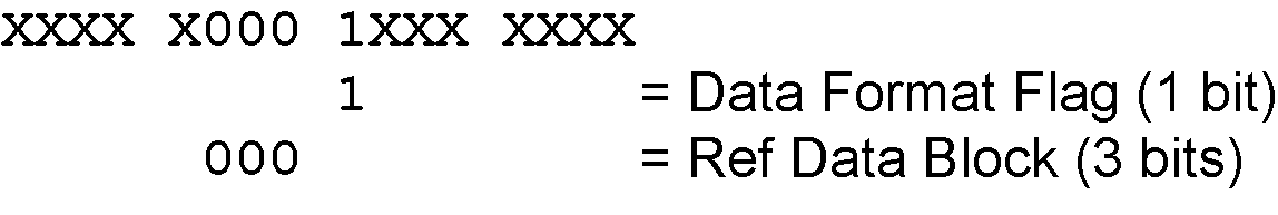
The Data Format Flag identifies that this batch of data is Differential (1) data.
The Ref Data Block ID is 0x000. The Ref Data Block ID here identifies that this differential data will be calculated from the Reference data that had a Ref Data Block ID equalling 000 (which was determined in the RANGECMP4 log at time 507977.00 seconds).
The 5 MSBs have not been processed so this byte will be carried forward.
Logs between seconds will be Differential logs but could be Reference logs depending on the compression calculations. If a discontinuity occurred that made it impossible for a Differential calculation to fit within the Differential Constraints, it will revert to a Reference log.
Differential measurement block
This block is sent once for each bit set to 1 in the Included Signals field found in Table: Satellite and signal block. Use Table: Primary differential signal measurement block and Table: Secondary differential signals measurement block to determine the contents of each field:
A Measurement Block for a single PRN will look like the following:
Primary Parity Flag
Primary ½ Cycle Slip Flag
Primary C/No
Primary Lock Time
Primary Pseudorange Std Deviation
Primary Phaserange Std Deviation
Primary Pseudorange
Primary Phaserange - Primary Pseudorange (determines the Phaserange for the 1st Signal)
Primary Doppler
2nd Parity Flag
2nd ½ Cycle Slip Flag
2nd C/No
2nd Lock Time
2nd Pseudorange Std Deviation
2nd Phaserange Std Deviation
2nd Pseudorange - Primary Pseudorange (determines the Pseudorange for the 2nd Signal
2nd Phaserange – 2nd Pseudorange (determines the Phaserange for the 2nd Signal)
2nd Doppler – Primary Doppler (determines the Doppler for the 2nd Signal)
3rd Parity Flag
3rd ½ Cycle Slip Flag
3rd C/No
3rd Lock Time
3rd Pseudorange Std Deviation
3rd Phaserange Std Deviation
3rd Pseudorange - Primary Pseudorange (determines the Pseudorange for the 3rd Signal
3rd Phaserange – 3rd Pseudorange (determines the Phaserange for the 3rd Signal)
3rd Doppler – Primary Doppler (determines the Doppler for the 3rd Signal)
…
Differential primary signal measurement block GPS PRN 10 – L1CA
The next bytes collected will be for the GPS PRN 10 - L1CA signal data. Since this is the primary signal of the PRN, its Measurement Block consists of 78 bits as listed in Table: Primary differential signal measurement block.
The signal info section (top 25 bits) is processed as follows:
-
With 5 bits left from the previous byte, we calculate 25 – 5 = 20 bits which rounds up to 3 bytes. Therefore the previous last byte (0x88) plus the next 3 bytes will be needed.
-
Use the last byte (0x88) plus grab 3 bytes (x831f61) = 0x88831f61
-
Swap the bytes = 0x611f8388
-
0x611f8388 in binary form
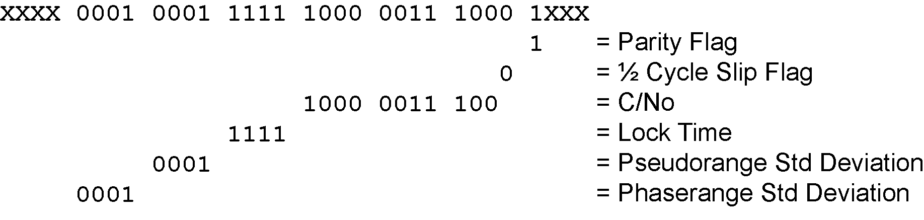
= 0110 0001 0001 1111 1000 0011 1000 1000
-
Only need 25 bits. The last byte uses the 5 MSBs and the first byte ignores the 4 MSBs
-
-
Parity flag is a 1 (Parity Known)
-
½ Cycle Slip flag is a 0 (Cycle Slip Not Present)
-
C/No is:
0x10000011100b = 1052 x Scaling factor of 0.05
= 52.60 dBHz -
The Lock Time value is:
0x1111b = 15 which means that this signal has been locked for 262144 ms or more. -
The Pseudorange Std Deviation value is:
0x0001b = 1 which means: 0.020 m < PSR Std Dev <= 0.030 m using Table: Pseudorange Std Dev. -
The ADR Std Deviation value is:
0x0001b = 1 which means: 0.0039 < ADR Std Dev <= 0.0052 cycles using Table: ADR Std DevTable 10. -
For the following calculations, the time difference between the Differential Log and the Reference log is 0.25 seconds as shown below:
Time Difference = Current Log Time – Reference log Time
= 507977.250 - 507977.000
= 0.250 seconds
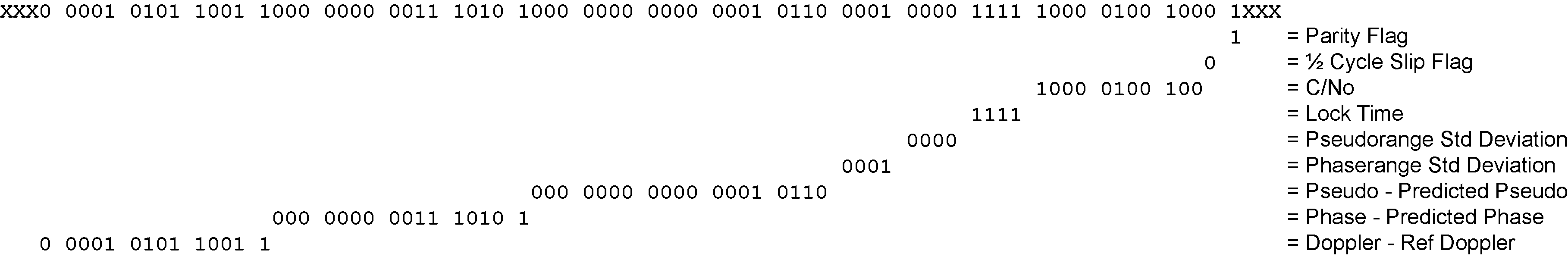
The signal data section (bottom 53 bits) is processed as follows:
-
With 4 bits unprocessed from the previous byte, we calculate 53 – 4 = 49 bits = 7 bytes (7 bits will not be processed in the last byte).
-
Use the last byte (0x61) plus grab 7 bytes (0x02005500e70162)
= 0x6102005500e70162 -
Swap the bytes = 0x6201e70055000261
-
0x6201e70055000261 in binary form =
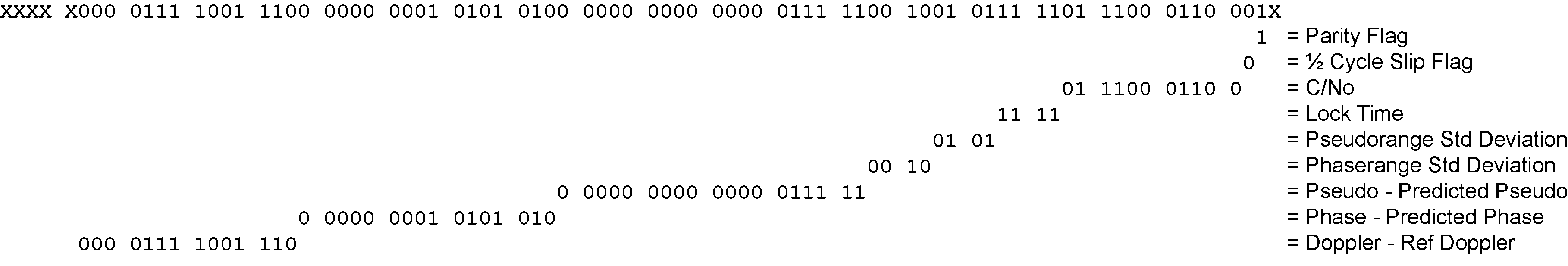
0110 0010 0000 0001 1110 0111 0000 0000 0101 0101 0000 0000 0000 0010 0110 0001
-
Only need 53 bits. Ignore last 4 LSBs and first 7 MSBs =

-
-
Use Table: Primary differential signal measurement block to identify if a 2’s Complement Conversion is needed as well as what Scale Factor should be used before these binary numbers are used in the following calculations.
-
The 1st (Primary) Differential Pseudorange is processed by:
Predicted Pseudorange = Reference 1st Pseudorange + (1st Doppler x TimeDifference)
= 21540181.930275 m
= 21540290.811 m + ((-435.5229 m/s) x 0.250 s)1st DiffPseudorange – Predicted Pseudorange = 0x0000000000000100110b x Scaling Factor
1st DiffPseudorange – 21540181.930275 m = 38 x 0.0005
L1CA Pseudorange for PRN 10 = 21540181.949275 m -
The 1st (Primary) Differential Phaserange is a 2’s Complement number (as identified by the Range column in Table: Primary differential signal measurement block) so it is processed in the following manner:
Predicted Phaserange = Reference 1st DiffPhaserange + (1st Doppler x TimeDifference)
= 21540291.5622 m + ((-435.5229 m/s) x 0.250 s)
= 21540182.681475 m1st DiffPhaserange – Predicted Phaserange = 2’s Complement(0x0000000010101010b) * Scaling Factor
1st DiffPhaserange – 21540182.681475 m = 170 * 0.0001
L1CA Phaserange = 21540182.698475 m -
Convert this to ADR to check against the original RANGE log:
ADR = 1st DifPhaserange * Frequency * (-1)/Speed Of Light
ADR = 21540182.698475 m * 1575420000 Hz * (-1)/299792458 m/s
L1CA ADR for PRN 10 = -113194424.0799796 cyclesIn the range logs, PSR and ADR have opposite signs.
-
The 1st (Primary) Differential Doppler is a 2’s Complement number (as identified by the Range column in Table: Primary differential signal measurement block) so it is processed in the following manner:
1st DiffDoppler(m/s)- Reference 1st Doppler = 2’s Complement(0x000000001111001110b) x Scaling Factor
1st DiffDoppler(m/s) – (-435.5229 m/s) = 974 x 0.0001
L1CA Doppler(m/s) = -435.4255 m/sConvert the Doppler to Hz:
1st DiffDoppler(Hz) = 1st DiffDoppler(m/s) x Frequency * (-1)/Speed Of Light
1st DiffDoppler(Hz) = -435.4255 m/s x 1575420000 Hz * (-1)/299792458 m/s
L1CA Doppler(Hz) for PRN 10 = 2288.1764464 Hz
Differential secondary signals measurement block GPS PRN 10 – L2Y
Unlike Reference logs which always reflect back to the initial signal for their computations, Differential logs uses the last Reference log data of the same signal for its calculations.
-
With 7 bits unprocessed from the previous byte, we will require 74 – 7 = 67 bits which rounds up to 9 bytes.
-
Use the last byte (0x62) plus grab the next 9 bytes (0xdc977c004015c07988)
= 0x62dc977c004015c07988 -
Swap the bytes = 0x8879c01540007c97dc62
-
0x8879c01540007c97dc62 in binary form =
1000 1000 0111 1001 1100 0000 0001 0101 0100 0000 0000 0000 0111 1100 1001 0111 1101 1100 0110 0010 -
Only need 74 bits. The 1 LSB is ignored as it was already processed above and the 5 MSBs are ignored so there is a total of 74 bits to process
-
-
Parity flag is a 1 (Parity Known)
-
½ Cycle Slip flag is a 0 (Cycle Slip Not Present)
-
C/No is:
0x01110001100b = 908 x Scaling Factor of 0.05
= 45.4 dBHz -
The Lock Time value is:
0x1111b = 15 which means that this signal has been locked for 262144 ms or more. -
The Pseudorange Std Deviation value is:
0x0101b = 5 which means: 0.099 m < PSR Std Dev <= 0.148 m using Table: Pseudorange Std Dev. -
The ADR Std Deviation value is:
0x0010b = 2 which means: 0.0052 < ADR Std Dev <= 0.0070 cycles using Table: ADR Std Dev. -
The L2Y Pseudorange is a 2’s Complement number (as identified by the Range column in Table: Secondary differential signals measurement block) so it is processed in the following manner:
Predicted Pseudorange = Reference 2nd Pseudorange + (2nd Doppler x TimeDifference)
= 21540293.6315 m + ((-435.523 m/s) x 0.250 s)
= 21540184.75075 mDiffPseudorange – Predicted Pseudorange = 2’s Complement(0x0000000000000011111b) x Scaling Factor
DiffPseudorange – 21540184.75075 m = 31 x 0.0005
L2Y Pseudorange = 21540184.76625 m -
The L2Y Phaserange is a 2’s Complement number (as identified by the Range column in Table: Secondary differential signals measurement block) so it is calculated in the following manner:
Predicted Phaserange = Reference 2nd DiffPhaserange + (2nd Doppler x TimeDifference)
= 21540294.399 m + ((-435.523 m/s) x 0.250 s)
= 21540185.51825 mDiffPhaserange – Predicted Phaserange = 2’s Complement(0x0000000010101010b) * Scaling Factor
DiffPhaserange – 21540185.51825 m = 170 * 0.0001
L2Y Phaserange = 21540185.53525 m -
Convert this to ADR to check against the original RANGE log:
ADR = Phaserange * Frequency * (-1)/Speed Of Light
ADR = 21540185.53525 m * 1227600000 Hz * (-1)/299792458 m/s
L2Y ADR for PRN 10 = -88203458.95116848 cyclesIn the range logs, PSR and ADR have opposite signs.
-
The L2Y Doppler is a 2’s Complement number (as identified by the Range column in Table: Secondary differential signals measurement block) so it is calculated in the following manner:
DiffDoppler(m/s) – Ref 2nd Doppler(m/s) = 2’s Complement(0x00001111001110b) x Scaling Factor
DiffDoppler(m/s) – (-435.5229 m/s) = (974) x 0.0001
L2Y Doppler(m/s) = -435.4255 m/sConvert the Doppler to Hz:
Doppler(Hz) = Doppler(m/s) x Frequency * (-1)/Speed Of Light
Doppler(Hz) = -435.4255 m/s x 1227600000 Hz * (-1)/299792458 m/s
L2Y Doppler(Hz) for PRN 10 = 1782.994633 Hz
Differential third signals measurement block GPS PRN 10 – L5Q
Unlike Reference logs which always reflect back to the initial signal for their computations, Differential logs uses the last Reference log data of the same signal for its calculations.
-
With 3 bits unprocessed from the previous byte, we will require 74 – 3 = 71 bits which rounds up to 9 bytes.
-
Use the last byte (0x88) plus grab the next 9 bytes (0x 840f6101803a805921)
= 0x88840f6101803a805921 -
Swap the bytes = 0x2159803a8001610f8488
-
0x2159803a8001610f8488 in binary form =
0010 0001 0101 1001 1000 0000 0011 1010 1000 0000 0000 0001 0110 0001 0000 1111 1000 0100 1000 1000 -
Only need 74 bits. The 3 LSBs are ignored as they were already processed and the 3 MSBs are ignored so there is a total of 74 bits to process.
-
-
Parity flag is a 1 (Parity Known)
-
½ Cycle Slip flag is a 0 (Cycle Slip Not Present)
-
C/No is:
0x10000100100b = 1060 x Scaling factor of 0.05
= 53.0 dBHz -
The Lock Time value is:
0x1111b = 15 which means that this signal has been locked for 262144 ms or more. -
The Pseudorange Std Deviation value is:
0x0000b = 0 which means: PSR Std Dev <= 0.020 m using Table: Pseudorange Std Dev. -
The ADR Std Deviation value is:
0x0001b = 1 which means: 0.0039 < ADR Std Dev <= 0.0052 cycles using Table: ADR Std Dev. -
The L5Q Pseudorange is a 2’s Complement number (as identified by the Range column in Table: Secondary differential signals measurement block) so it is processed in the following manner:
Predicted Pseudorange = Reference 3rd Pseudorange + (3rd Doppler x TimeDifference)
= 21540289.869 m + ((-435.5149 m/s) x 0.250 s)
= 21540180.990275 mDiffPseudorange – Predicted Pseudorange = 2’s Complement(0x000 0000 0000 0001 0110b) x Scaling Factor
DiffPseudorange – 21540180.990275 m = 22 x 0.0005
L5Q Pseudorange = 21540181.001275 m -
The L5Q Phaserange is a 2’s Complement number (as identified by the Range column in Table: Secondary differential signals measurement block) so it is calculated in the following manner:
Predicted Phaserange = Reference 3rd DiffPhaserange + (3rd Doppler x TimeDifference)
= 21540290.8584 m + ((-435.5149 m/s) x 0.250 s)
= 21540181.979675 mDiffPhaserange – Predicted Phaserange = 2’s Complement(0x0000000001110101b) * Scaling Factor
DiffPhaserange – 21540181.979675 m = 117 * 0.0001
L5Q Phaserange = 21540181.991375 m -
Convert this to ADR to check against the original RANGE log:
ADR = Phaserange * Frequency * (-1)/Speed Of Light
ADR = 21540181.991375 m * 1176450000 Hz * (-1)/299792458 m/s
L5Q ADR for PRN 10 = -84528300.92127641 cyclesIn the range logs, PSR and ADR have opposite signs.
-
The L5Q Doppler is a 2’s Complement number (as identified by the Range column in Table: Secondary differential signals measurement block) so it is calculated in the following manner:
DiffDoppler(m/s) – Ref 3rd Doppler(m/s) = 2’s Complement(0x00001010110011b) x Scaling Factor
DiffDoppler(m/s) – (-435.5149 m/s) = 691 x 0.0001
L5Q Doppler(m/s) = -435.4458 m/sConvert this to Hz:
Doppler(Hz) = Doppler(m/s) x Frequency * (-1)/Speed Of Light
Doppler(Hz) = -435.4458 m/s x 1176450000 Hz * (-1)/299792458 m/s
L5Q Doppler(Hz) for PRN 10 = 1708.78285 Hz
This concludes the decoding of the Differential Log for PRN 10 (signals L1CA, L2Y, and L5Q). The rest of the decoding for the other PRNs and systems are handled in the same manner.