Single antenna supplying multiple receivers
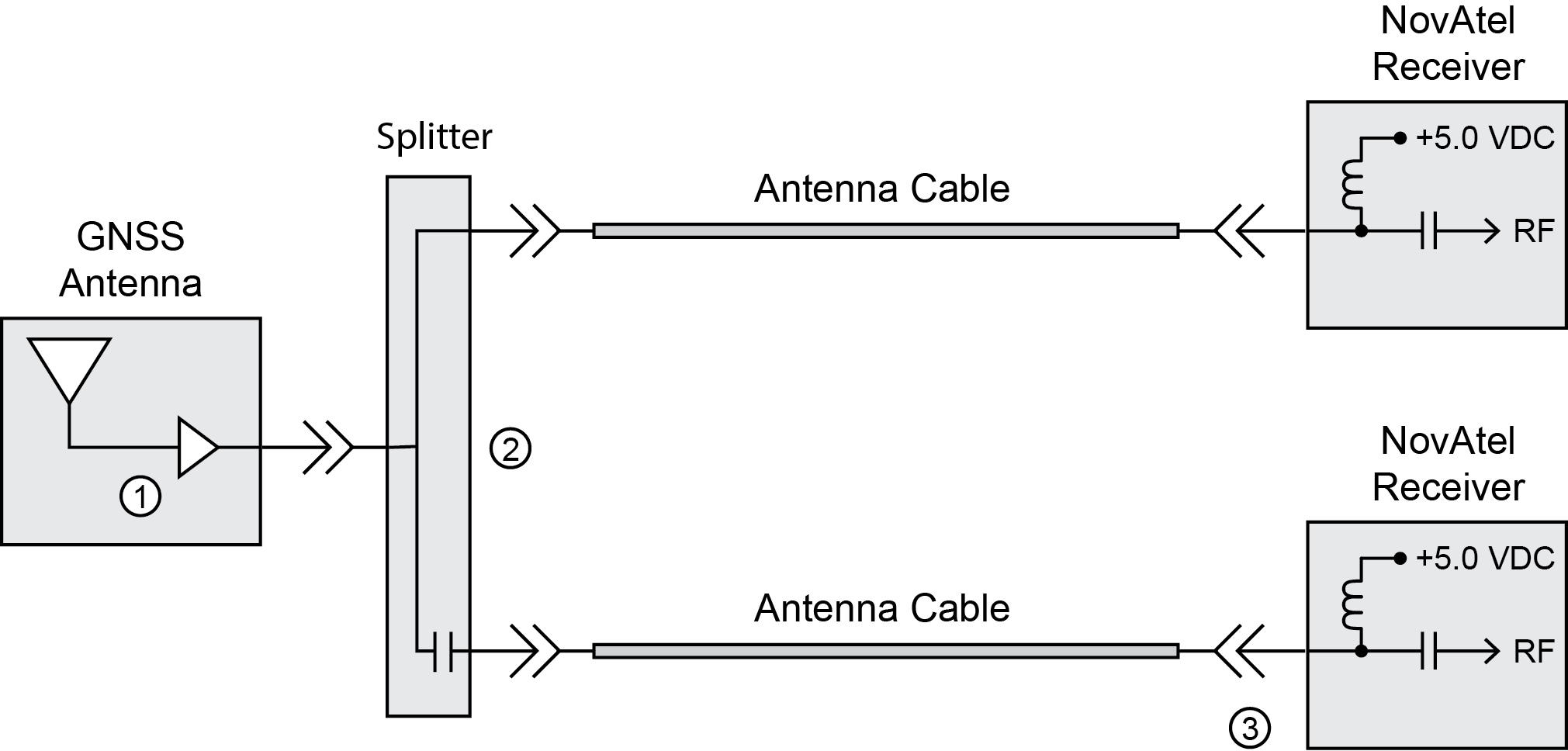
If a single antenna is to be connected to multiple receivers, a splitter must be inserted between the antenna and the receivers. Figure: Single antenna to multiple receivers illustrates a typical setup using a splitter to provide two receivers with the GNSS signal. The splitter is designed so that one of the receivers provides power to the antenna while the other is blocked so no DC power passes from it to the antenna or back to the first receiver.
Single antenna to multiple receivers
|
1 |
Most GNSS antenna LNAs safely operate with +5.0 VDC input voltage. |
|
2 |
The splitter allows DC power from the top receiver to feed the antenna. It prevents DC power from the bottom receiver from moving to the antenna or back to the top receiver. |
|
3 |
The ANTENNAPOWER OFF command must be issued to the receiver that is not powering the antenna to disable the receiver’s internal LNA power output. |
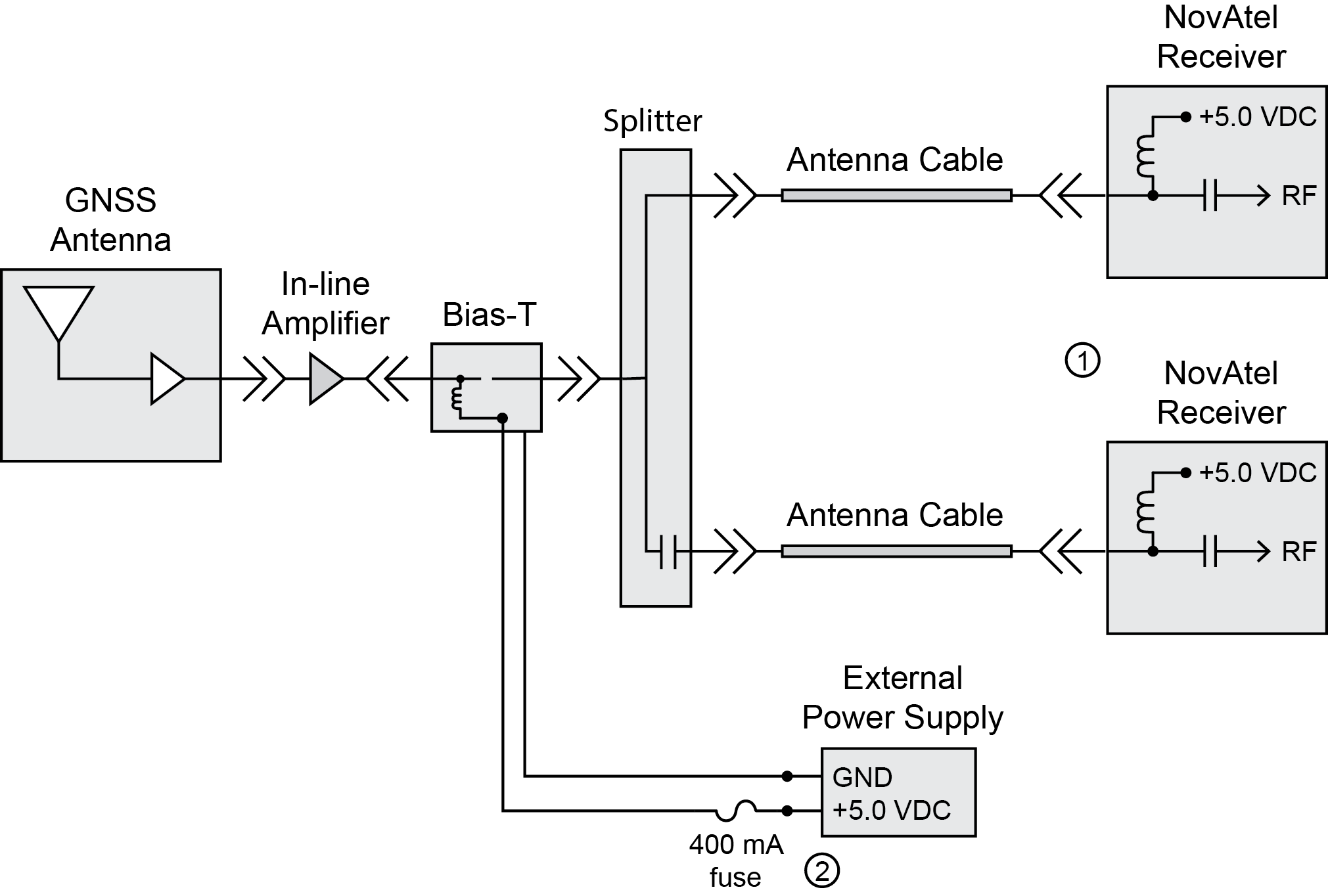
If the overall gain at the receiver is less than +15 dB due to the addition of the splitter and any other equipment introduced, an in-line amplifier must be installed between the antenna LNA and the splitter, where the signal to noise ratio is at its highest. For example, if the antenna provides +30 dB of gain, the connection between the antenna and the splitter introduces -5 dB loss, the splitter adds -5 dB loss and the cable between the splitter and receiver reduces the signal by -10 dB, amplification by at least +5 dB is required to yield the minimum input gain requirement of +15 dB; to attain a net RF input gain of +25 dB, then +15 dB of amplification would be required. Figure: Single antenna to multiple receivers with in-line amplifier shows an in-line amplifier requiring an external supply and, therefore, a bias-T. The bias-T should include circuitry to prevent DC power from being fed back to the receiver and the ANTENNAPOWER OFF command must be issued to disable the internal LNA power supply on both receivers. See Low input gain for other installation solutions based on the power requirements of the in-line amplifier.
Single antenna to multiple receivers with in-line amplifier
|
1 |
The ANTENNAPOWER OFF command must be issued to each of the receivers to disable the receivers’ internal LNA power output. |
|
2 |
The fusing and power supply requirements depend on the in-line amplifier and antenna. 400 mA and +5.0 VDC are examples shown for illustration purposes only. |