Insufficient cable length
In some cases, the 30 metre RF cable available from NovAtel is not long enough. There are two basic methods that facilitate longer antenna cable runs:
-
Selecting specialized low-loss coaxial cables (passive method)
-
Inserting additional cable lengths and adding in-line, low noise amplifiers between the GNSS antenna, antenna cable, and receiver to keep the net gain at an acceptable level (active method).
Passive cable runs
The passive method of extending the remote location of the GNSS antenna is achieved by selecting a high quality coaxial cable exhibiting low loss over extended lengths, as shown in Figure: Extended length, low-loss antenna cable. Distances of 200 to 300 metres (656 to 984 feet) are possible by this method. The most important factor in selecting the cable is that its maximum loss over the desired length still provides for at least +15 dB (+20 dB if HDR Mode is enabled), and preferably +25 dB of gain at the receiver’s RF input.
Extended length, low-loss antenna cable

|
1 |
The antenna LNA is powered by +5.0 VDC from the receiver via the antenna cable center conductor. |
One major disadvantage of specialized low-loss cables for long runs is that typically a larger diameter cable is required to reduce the signal losses. This in turn means that heavier, more rigid cable construction is required to manufacture the cable. Weight and flexibility may be a major factor in the practical limit for the cable length. A sharp rise in the cost per metre accompanies low-loss cables since special manufacturing methods and materials are required. Eventually, as distances become greater, a practical limit is reached where cost, weight, and rigidity become prohibitive factors.
Active cable runs
In some cases, long cable runs may become more practical by using "active" methods. Increasing the distance between the GNSS antenna and receiver by active means is accomplished by inserting one or more additional cable lengths and adding an in-line amplifier to negate the signal loss of each additional cable length.
The use of in-line amplifiers allows for smaller, less expensive, and more flexible coaxial cable as opposed to the larger, semi-rigid, low-loss cables. On the other hand, a good deal more hardware is required for the installation, such as one or more in-line amplifiers, an external power supply system for the amplifiers and possibly a DC block, coaxial connector adapters, and a bias-T to inject the external power supply through the coaxial cable.
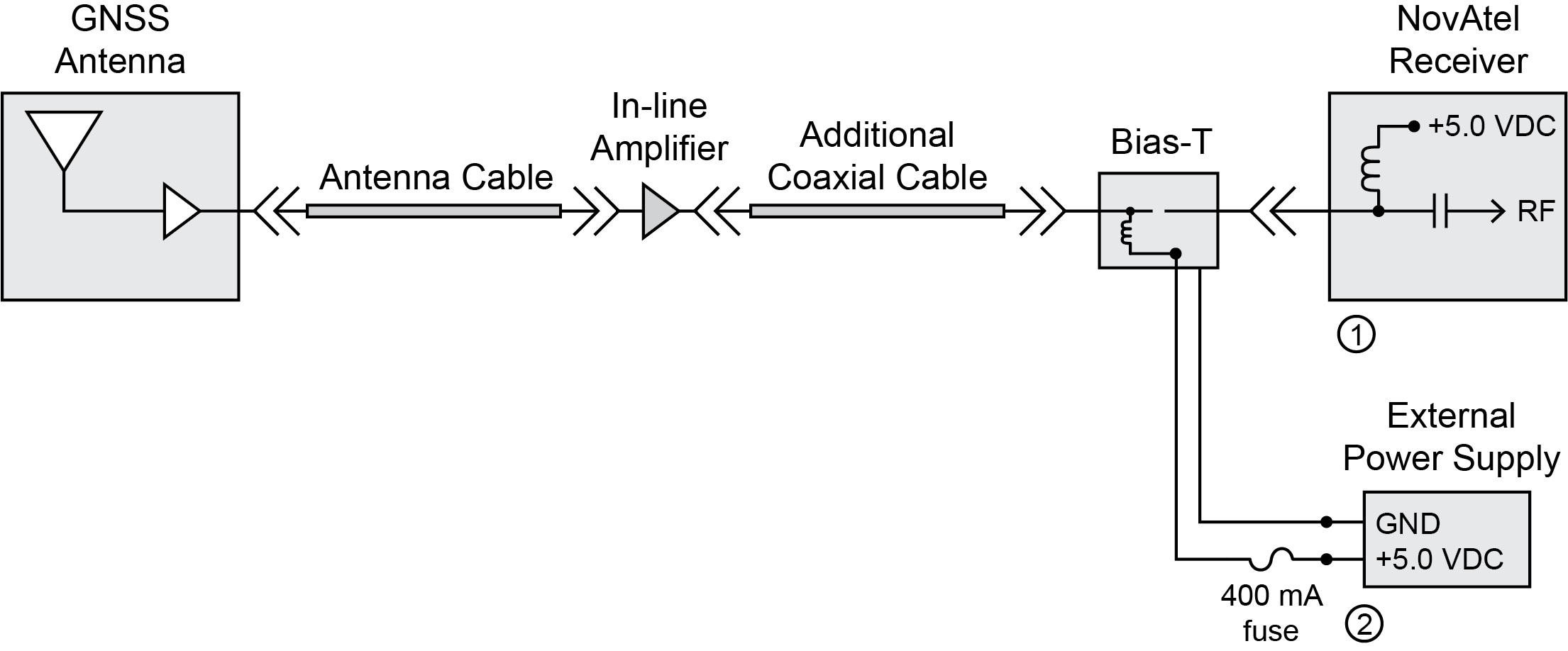
A basic installation using an in-line amplifier powered by an external power supply through a bias-T is shown in Figure: Additional cable length with in-line amplifier. The bias-T should include circuitry to prevent DC power from being fed back to the receiver. Because an external supply is being used, the receiver’s internal LNA power output must be disabled using the ANTENNAPOWER OFF command. However, depending on the power requirements of the in-line amplifier and antenna, one of the other solutions for incorporating in-line amplifiers as discussed in Special cases may be more suitable.
Proper fusing or current limiting should be incorporated in the external power supply line.
Additional cable length with in-line amplifier

|
1 |
The ANTENNAPOWER OFF command must be issued to the receiver to disable the receiver’s internal LNA power output. |
|
2 |
The current and voltage requirements of your RF equipment may vary. The 400 mA fuse and +5.0 VDC supply shown are for illustration purposes only. |