Interference Toolkit
|
Platform: |
OEM719, OEM729, OEM7500, OEM7600, OEM7700, OEM7720, PwrPak7, CPT7, CPT7700, SMART7, SMART2 |
The Interference Toolkit (ITK) feature monitors, quantifies and removes interference sources to prevent interference from impacting receiver performance.
Using the Interference Toolkit, you can monitor the Radio Frequency (RF) spectrum in a range of frequencies around the GNSS signals that are being received by the OEM7 receiver. If an interference signal is detected, information about the interference is output in the ITDETECTSTATUS log. More information about the interference signal can be determined by plotting the information obtained.
Signals available are model dependent. A variety of mitigation techniques are available. Contact novatel.com/contactus/sales-offices to activate full mitigation features.
Monitoring GNSS signals
By default, interference detection is enabled. Detection can be disabled/enabled as needed. See Disable/Enable detection for instructions. Detected interference can be viewed and different tracking modes with possible additional filters can be applied to mitigate the interference using NovAtel Application Suite. Detected interference details can also be logged and analysed using the command line interface.
There are two types of interference detection available, Spectral Analysis Detection and Statistical Analysis Detection.
NovAtel recommends using the default settings for Interference Toolkit whenever possible.
Spectral analysis detection
Spectral Analysis Detection is focused on in-band, near-band, and strong out-band interference detection.
OEM7 uses receiver gain calibration data that is stored in receiver memory at receiver start-up. The calibration data is used to estimate the antenna gain before the receiver, as well as generate interference free spectrum reference for spectral analysis detection. The receiver assumes that the receiver is in an interference free environment during start-up and the antenna is connected to the receiver and powered up.
When using the Interference Toolkit, the receiver must be reset when the GNSS antenna is connected or disconnected.
If a known interference source is present at the receiver start up, it's strongly recommended that users enter the calibrated receiver input gain using the RFINPUTGAIN command.
Measuring the RF input gain
This section is intended for advanced users.
The RFINPUTGAIN command allows users to enter a more accurate receiver input condition, which is considered as a calibrated receiver input condition, and is used for interference detection. This command supports different values for L1, L2, L5, and L-band and is recommended when there is a known strong interference present at receiver start up.
To calibrate the receiver input level, use a standard spectrum analyser to measure the receiver input noise density in dBm/Hz. Make sure the pre-amplifier is turned on in Spectrum Analyser under “Amplitude”. Place the Marker around L1, L2, L5, or L-band frequency region and select “noise density” under “Marker Function”.
RFINPUTGAIN = Receiver Input Noise Density (dBm/Hz) - Typical Thermal Noise KT of -174dBm/Hz,
where:
K = 1.38E-23w-sec/K
T = 290 k.
For example, if the receiver input noise density measured at L1 is -144dBm/Hz,
RFINPUTGAIN = -144 – (-174) = 30dB for L1 path.
Alternatively, if a spectrum analyser is not available, the RFINPUTGAIN can be obtained using the cascaded RF gain before the receiver plus LNA noise figure (NF), including LNA gain in antenna, in-line amplifier gain (if applicable), RF cable or distribution loss prior to receiver input connector. A typical GNSS active antenna with reasonable quality has a noise figure of ~2dB.
RFINPUTGAIN = Cascaded Gain before receiver + LNA NF
For example, if system cumulative gain measured before receiver is ~25dB, and LNA NF is around 2dB, the RFINPUTGAIN = 27dB.
RFINPUTGAIN L1 27
RFINPUTGAIN L2 27
RFINPUTGAIN L5 27
RFINPUTGAIN LBand 27
Statistical analysis detection
Statistical Analysis Detection is focused on out of band interference detection. It is supplementary to the Spectrum Analysis Detection and is useful when interference is outside the analog passband of the receiver and creating distortion that may not be visible to Spectrum Analysis Detection until the interference is very strong.
The Statistical Analysis Detection is designed as a sensitive detection tool. Out of band mitigation does not impose much penalty when enabled and it brings awareness to unintentional interferences next to GNSS operations.
Spectral Analysis Detection takes precedent over Statistical Analysis Detection. If the same interference is detected by both detectors, only Spectral Analysis Detection is used to report the interference status.
Disable/Enable detection
The interference detection feature can be enabled/disabled from the command line using the ITDETECTCONFIG command.
To disable interference detection, enter:
ITDETECTCONFIG none
To enable interference on all RF paths, enter :
ITDETECTCONFIG all
Interference detection can also be enabled on individual RF paths. See the ITDETECTCONFIG command for details.
The sensitivity level for setting the Jammer Detected bit in the Receiver Status word in the log headers can be configured using the ITWARNINGCONFIG command. By default it is set to the least sensitive setting, meaning that interference needs to be severe for this bit to be set.
Monitoring signals using the command line
The ITDETECTSTATUS log lists all detected interference signals. For interference detected by spectral analysis, the log also provides the centre frequency and bandwidth of the interference signal. With this information, a filter can be configured to mitigate the interference.
Due to the high volume of data, a higher bandwidth medium, such as USB or Ethernet, is recommended when monitoring signals using the Interference Toolkit.
Example:
LOG ITDETECTSTATUS onchanged
#ITDETECTSTATUSA,USB2,0,74.0,FINESTEERING,1982,430605.267,0200c000,7fdb,32768;3,L1,STATISTICANALYSIS,-0.718,29.167,0.126,12.797,00000000,00000000,00000000,L2,SPECTRUMANALYSIS,1249.961,71.191,-56.769,-132.907,00000000,00000000,00000000,L2,SPECTRUMANALYSIS,1289.512,1.978,-75.967,-138.493,00000000,00000000,00000000*87381101
In the above example, there are three interference signals detected:
-
Out of band interference near L1 (STATISTICANALYSIS)
-
Interference in the L2 band at 1249.961 MHz
-
Interference in the L2 band at 1289.512 MHz
To view details about the signals that are being received by the OEM7 receiver and determine if there is an interference signal within the GNSS signals, use the ITSPECTRALANALYSIS command to enable and configure the spectral analysis. The spectrum can then be viewed by plotting the PSD samples in the ITPSDFINAL log. NovAtel Application Suite can also be used to view the spectrum. See Monitoring signals using NovAtel Application Suite.
Example:
ITSPECTRALANALYSIS PREDECIMATION GPSL1 200 2K 1 1
LOG ITPSDFINAL onnew
When logged, incoming signal information is collected at the rate specified in the ITSPECTRALANALYSIS command.
Pre-decimation – Raw analog-to-digital converter signals.
Post-decimation – Analog-to-digital converted signal for the specific signal encoder path. This gives a narrower view of the incoming signal.
Monitoring signals using NovAtel Application Suite
Due to the high volume of data, a higher bandwidth medium, such as USB or Ethernet, is recommended when monitoring signals using the Interference Toolkit.
Start NovAtel Application Suite and open a Manage connection to the OEM7 receiver.
Click Tools and select Interference Toolkit. The Interference Toolkit window opens. The following example shows a typical signal.
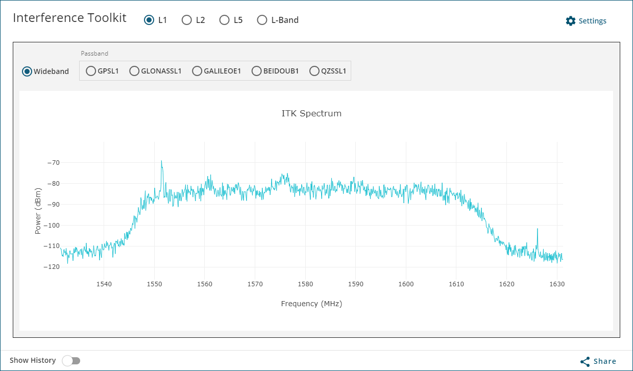
Placing the cursor over any place in the signal band will display additional information regarding that location in the signal band.
For information about using the Interference Toolkit in NovAtel Application Suite, refer to docs.novatel.com/Tools/Content/Manage/InterferenceToolKit.htm.
Remove interference signals
If an interference signal is present, the Interference Toolkit can reduce or eliminate the impact on GNSS tracking using the programmable High Dynamic Range (HDR), Bandpass or Notch filters.
Contact novatel.com/contactus/sales-offices to obtain mitigation functionality.
High Dynamic Range mode
The High Dynamic Range (HDR) mode enables special signal processing to remove distortions from the spectrum, providing a cleaner signal. This optimizes the Automatic Gain Control (AGC) to prevent interfering signals from drowning out the GNSS signals. HDR mode works well against wide band and out-of-band interferers. HDR mode can be combined with bandpass and notch filters, but does draw more power.
To configure HDR mode, use the ITFRONTENDMODE command. HDR mode can also be enabled using NovAtel Application Suite.
Notch filter
The Interference Toolkit notch filter reduces the signal power in a narrow frequency band. This type of filter is useful for reducing the signal power of a single, narrow band interference signal. Note that the narrowest possible filter should be used to maintain the maximum amount of overall signal power.
To configure a notch filter, use the ITPROGFILTCONFIG command. A notch filter can also be configured using NovAtel Application Suite.
Bandpass filter
The Interference Toolkit bandpass filter reduces the signal power of all incoming signals at the upper and lower end of the GNSS signal band starting at the requested cut-off frequency. This type of filter is good for reducing single or multiple interference signals at the edges of the signal band.
When a bandpass filter is applied to this signal, the upper and lower ends of the signal band are filtered out to reduce the signal power of the interference signal.
To configure a bandpass filter, use the ITPROGFILTCONFIG command or the ITBANDPASSCONFIG command. A bandpass filter can also be configured using NovAtel Application Suite.
Interference Toolkit commands and logs
The following are the commands and logs used by the Interference Toolkit to monitor, apply filters and mitigate interference. Commands and logs with the √ are available by default. Contact novatel.com/contactus/sales-offices to activate full mitigation features.
|
Commands |
||
|---|---|---|
|
|
Configures a bandpass filter on the receiver. |
|
|
√ |
Enables or disables automatic interference detection on the receiver. |
|
|
|
Configures the front end mode for each RF path to use the default tracking mode or change to High Dynamic Range (HDR) mode. |
|
|
|
Configures filtering on the receiver to be either a notch filter or a bandpass filter. |
|
|
√ |
Configures and enables spectral analysis on the receiver. |
|
|
√ |
Configures the interference detection threshold on the receiver. |
|
|
Logs |
||
|---|---|---|
|
|
Provides the allowable bandpass filter configurations. |
|
|
√ |
Lists all of the interference detected on the paths on which automatic interference detection has been enabled. |
|
|
|
Summarizes the filter configuration for each frequency and indicates which bandpass or notch filters are enabled and configured. |
|
|
|
Provides the allowable programmable filter configurations. |
|
|
√ |
Provides the power spectral density information of the specified signal path. |
|